
Prosthetic capsular devices, systems, and methods

a technology of capsular devices and capsular stents, applied in the field of prosthetic capsular devices, can solve the problems of inability to account for the major variability problem, the recovery of visual function, and the increase of the precision of the femtosecond laser system, and achieve the effect of affecting wear

Active Publication Date: 2016-06-07
OMEGA OPHTHALMICS
View PDF147 Cites 79 Cited by
  • Summary
  • Abstract
  • Description
  • Claims
  • Application Information

AI Technical Summary

Benefits of technology

The patent describes methods and devices for placing a wearable electronic device in the eye. These devices can be used for various functions such as internet access, computer functions, and healthcare monitoring. The devices can be inserted into a prosthetic capsular device that can be surgically removed from the natural capsule in the eye. The prosthetic capsular device can also include an intraocular lens. The technology device can be positioned in the eye without interfering with the sight lines through the lens. The patent also describes the use of a retinal prosthesis in a prosthetic capsular device. Overall, the patent provides methods and devices for safely and reliably placing electronic devices in the eye.

Problems solved by technology

The procedure takes a short amount of time to perform, and patients expect quick recovery of visual function.
Despite accurate preoperative measurements and excellent surgical technique, the desired refractive outcome requires a dose of good fortune as there are numerous uncontrolled variables involved.
Unfortunately, the increased precision of the femtosecond laser systems have not been able to account for the major problem plaguing the variability of the ELP, which is the volumetric difference between the cataract, natural capsular bag, and intraocular lens implant (IOL).
Such body-mounted devices can be awkward to wear and some users might prefer the positioning of the device in the body.
In some implementations in which the retinal prosthesis can function as the end receptor of light, the retinal prosthesis may interfere with (e.g., block, distort) the sight lines through the IOL.

Method used


Image

  • Prosthetic capsular devices, systems, and methods
  • Prosthetic capsular devices, systems, and methods
  • Prosthetic capsular devices, systems, and methods

Examples


Embodiment Construction

[0194]Some prosthetic capsular enclosure devices (e.g., prosthetic capsular bags) that can be used in the eye can hold at least one of a technology device (e.g., an electronic technology device (e.g., a wearable electronic technology device (e.g., a miniaturized wearable electronic technology device))) and an intraocular lens.

[0195]Examples of preferred prosthetic capsular devices that may be compatible with certain implementations described herein are disclosed in PCT Published Patent Application No. WO 2013 / 126380, which is incorporated herein by reference in its entirety. Some preferred prosthetic capsular devices are described herein.

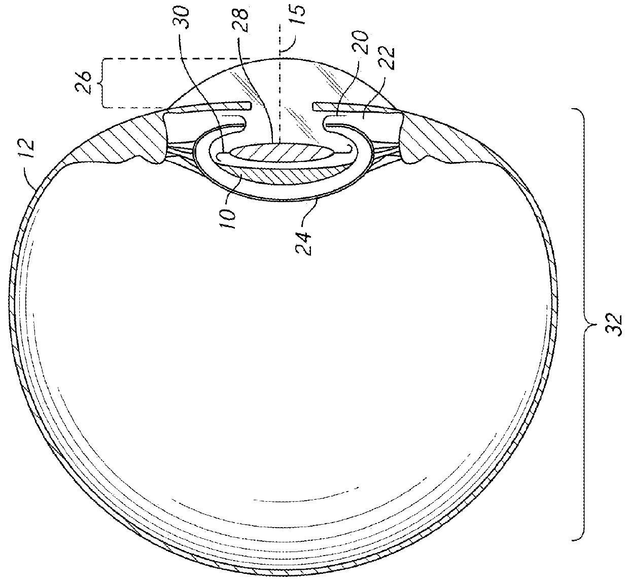
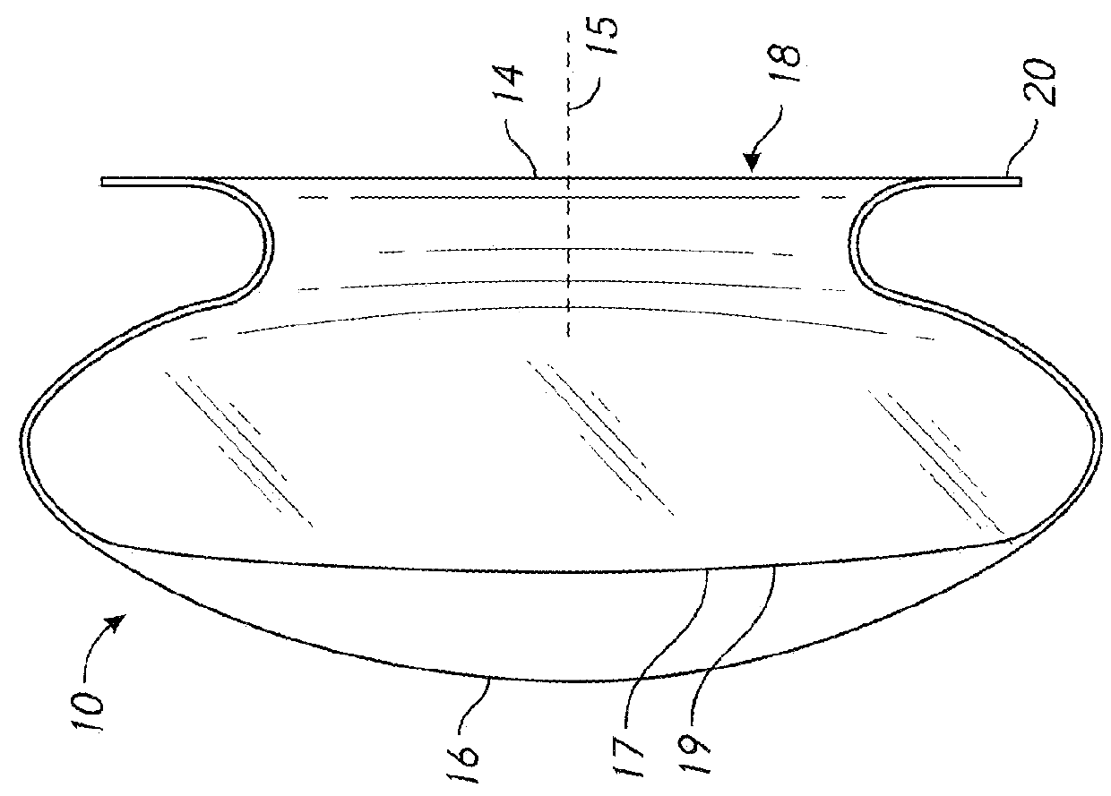
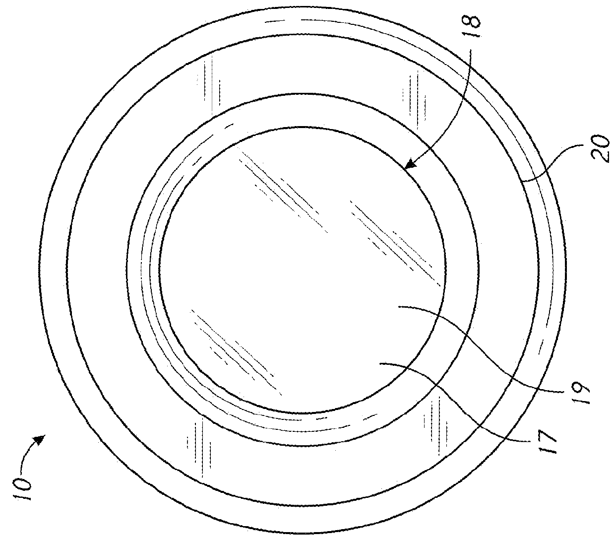
[0196]With reference to FIGS. 1-3, a prosthetic capsular device or PPL-C 10 is shown approximating the size, shape, and volume of a natural human lens. The dimensions of the prosthetic capsular device 10 may be variable, so that physicians may order an implant that most closely matches the lens of the eye 12 being operated on. The human lens varies ...


PUM


Abstract

A prosthetic capsular device configured to be inserted in an eye includes a housing structure and a ring structure. The housing structure includes a first side, a second side opposite the first side, a third side, a fourth side opposite the third side, a posterior side including a refractive surface, an anterior side opposite the posterior side, and a longitudinal axis. The first side, the second side, the third side, the fourth side, the posterior side, and the anterior side at least partially define a cavity configured to contain an intraocular device (e.g., an IOL). The anterior side includes an opening. The ring structure includes a ring structure portion extending radially outward from proximate one of an end of the first side and an end of the second side.

Description

INCORPORATION BY REFERENCE TO ANY PRIORITY APPLICATIONS[0001]This application is related to U.S. Provisional Patent Application No. 62 / 216,591, filed Sep. 10, 2015, U.S. Provisional Patent Application No. 62 / 168,493, filed May 29, 2015, and U.S. Provisional Patent Application No. 62 / 114,231, filed Feb. 10, 2015, each of which is incorporated herein by reference in its entirety. Any and all applications for which a foreign or domestic priority claim is identified in the Application Data Sheet as filed with the present application are hereby incorporated by reference under 37 C.F.R. §1.57.BACKGROUND[0002]1. Technical Field[0003]The present application relates to prosthetic capsular devices including wearable electronic technology device(s), and methods for insertion into the eye.[0004]2. Description of the Art[0005]Cataract surgery is one of the most successfully and most frequently performed surgical procedures in the United States. Each year, millions of people achieve a dramatic im...

Claims


Application Information

Patent Timeline
IPC IPC(8): A61F2/16
CPCA61F2/1694A61F2/16A61F2002/1681A61F2002/16902A61F2002/169A61F2002/16901A61F2/1648A61F2002/1689A61F2220/0075A61F2250/0068A61F2210/0014A61F2/1691A61F2/14A61F2220/0033A61F9/0017
Inventor WORTZ, GARY N.IFLAND, RICK WILLIAM
Owner OMEGA OPHTHALMICS
Features
  • Generate Ideas
  • Intellectual Property
  • Life Sciences
  • Materials
  • Tech Scout
  • Unparalleled Data Quality
  • Higher Quality Content
  • 60% Fewer Hallucinations
Learn More