Method and device for calculating a flight plan of an aircraft in a runway approach phase

a flight plan and runway approach technology, applied in the field of flight management systems, can solve the problems of not being able to have continuity, day implementations that do not make it possible to link divergent parts of flight plans, and not being able to have 2 days implementations

Active Publication Date: 2016-06-14
THALES SA
View PDF17 Cites 3 Cited by
  • Summary
  • Abstract
  • Description
  • Claims
  • Application Information

AI Technical Summary

Problems solved by technology

A major disadvantage is that, when the end point of the MAP type does not correspond with the runway threshold, the crew has to manage the end of the approach manually in order to join the runway from the end point.
A major disadvantage is that the present-day systems do not make it possible to have a continuity of the flight plan (and therefore of the reference trajectory) allowing the aircraft to be guided continuously according to the initial approach procedure ending at the MAP (which is not the threshold of the runway) and then according to the additional company procedure up to the runway.
In fact, present-day implementations do not make it possible to have 2 points of the MAP type in the same flight plan: the first MAP point is on the one hand the end of the activated part of the primary flight plan (initial approach procedure) and the start of the associated “Missed Approach” part MA1.
The present-day implementations do not make it possible to link divergent parts of flight plan.
However, there are rules which prohibit the activation of the secondary flight plan.
This activation necessitates a series of complex operations by the pilot during the critical phase of the landing, which cannot be done in practice.
Thus, there is no guidance by the FMS in this case, either laterally or vertically, since the activated primary flight plan is no longer being followed.

Method used


Image

  • Method and device for calculating a flight plan of an aircraft in a runway approach phase
  • Method and device for calculating a flight plan of an aircraft in a runway approach phase
  • Method and device for calculating a flight plan of an aircraft in a runway approach phase

Examples


Embodiment Construction

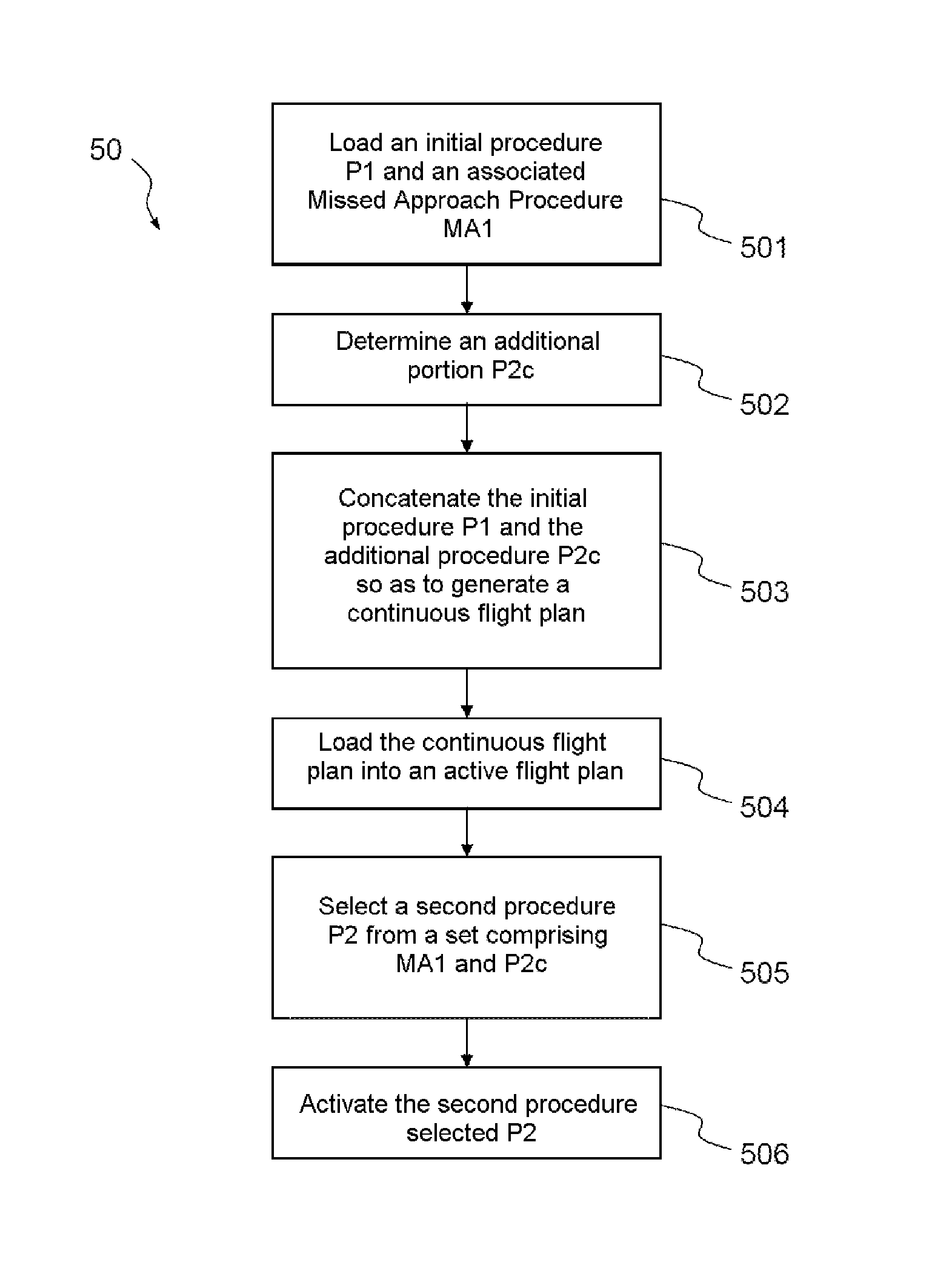
[0077]FIG. 5 describes the steps of the method 50 according to the invention. The method 50 calculates a flight plan of an aircraft used by a flight management system (FMS) capable of being used during a runway approach and up to the point Pa corresponding to the threshold of the runway.

[0078]The method according to the invention comprises a first step 501 of loading an initial procedure P1 ending at a first end point C1 not corresponding to the threshold Pa of the runway. The approach procedure P1 is therefore typically a published procedure previously stored in the navigation database 103 and then inserted in the flight plan de the aircraft.

[0079]As previously described in the prior art, the point C1 is a point of the MAP type and therefore an associated “Missed Approach”, called the first missed approach procedure MA1, is also inserted in the flight plan de the aircraft.

[0080]Thus, the method according to the invention comprises a step 501 of loading an initial procedure P1 and i...


PUM


Abstract

A method for calculating a flight plan used by a flight management system of an aircraft in a runway approach phase comprises: loading an initial procedure ending at a first end point not corresponding to a threshold of the runway and a first associated missed approach procedure; determining an additional procedure and a second associated missed approach procedure; concatenating the initial procedure and the additional procedure in order to generate a continuous concatenated flight plan comprising the initial procedure, the first missed approach procedure, the additional procedure and the second missed approach procedure; loading the concatenated flight plan into an active flight plan; selecting a second procedure from a set comprising the first missed approach procedure and the additional procedure; activating the selected second procedure.

Description

CROSS-REFERENCE TO RELATED APPLICATION[0001]This application claims priority to foreign French patent application No. FR 1301521, filed on Jun. 28, 2013, the disclosure of which is incorporated by reference in its entirety.FIELD OF THE INVENTION[0002]The present invention relates to the field of equipment of a Flight Management System, usually referred to as an FMS. More precisely, the present invention relates to a method and a device for calculating a portion of a flight plan used by the FMS when an aircraft is in a runway approach phase, more particularly when the initial approach procedure does not end at the runway but at a certain distance from the latter.BACKGROUND[0003]When preparing the flight or a diversion, the crew enters its flight plan on a dedicated computer: the FMS (Flight Management System).[0004]FIG. 1 shows the different components of an FMS having functions as listed below and described in the standard ARINC 702 (Advanced Flight Management Computer System, Decem...

Claims


Application Information

Patent Timeline
Patent Type & Authority Patents(United States)
IPC IPC(8): G08G5/02G05D1/06G08G5/00
CPCG08G5/02G05D1/0676G08G5/0039G08G5/025
Inventor COULMEAU, FRANCOISSACLE, JEROMEDEWAS, EMMANUEL
Owner THALES SA
Why Eureka
Try Eureka