Dual-coupled phase-locked loops for clock and packet-based synchronization

a phase-locked loop and clock technology, applied in the field of integrated circuit devices, can solve the problems of not being able to align frame pulses and timing pulses across a network using just sync, requiring a relatively long adjustment time for larger phase changes, and wandering

Active Publication Date: 2016-06-14
INTEGRATED DEVICE TECH INC
View PDF4 Cites 29 Cited by
  • Summary
  • Abstract
  • Description
  • Claims
  • Application Information

AI Technical Summary

Benefits of technology

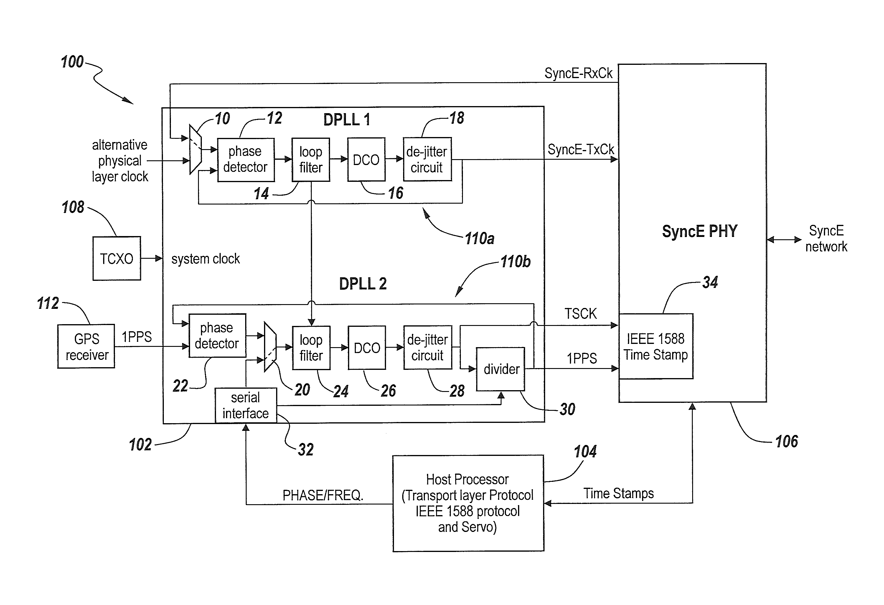
The technical effect of this patent is that it describes how two different loops are used for locking onto frequencies. A first loop includes filters and control circuits to adjust the frequency, while a second loop provides more precise fine tuning. These loops work together seamlessly without interfering or causing delays during the process.

Problems solved by technology

The technical problem addressed in this patent text relates to finding more flexible methods of combining a sync E clock and IEEE 1588 protocols without requiring them to share a common primary timing reference.

Method used


Image

  • Dual-coupled phase-locked loops for clock and packet-based synchronization
  • Dual-coupled phase-locked loops for clock and packet-based synchronization
  • Dual-coupled phase-locked loops for clock and packet-based synchronization

Examples


Embodiment Construction

[0030]The present invention now will be described more fully with reference to the accompanying drawings, in which preferred embodiments of the invention are shown. This invention may, however, be embodied in many different forms and should not be construed as being limited to the embodiments set forth herein; rather, these embodiments are provided so that this disclosure will be thorough and complete, and will fully convey the scope of the invention to those skilled in the art. Like reference numerals refer to like elements throughout.

[0031]It will be understood that when an element or layer is referred to as being “on,”“connected to” or “coupled to” another element or layer (and variants thereof), it can be directly on, connected or coupled to the other element or layer or intervening elements or layers may be present. In contrast, when an element is referred to as being “directly on,”“directly connected to” or “directly coupled to” another element or layer (and variants thereof),...


PUM


Abstract

A Synchronous Ethernet (SyncE) network device includes a pair of phase-locked loops including a first phase-locked loop responsive to a SyncE input clock and a second phase-locked loop coupled to the first phase-locked loop. The second phase-locked loop is configured to be simultaneously lockable to both the SyncE input clock via the first phase-locked loop and an IEEE 1588 packet stream, during a locked mode of operation, and also lockable to the SyncE input clock during a holdover mode of operation which is triggered in response to a failure of the IEEE 1588 packet stream.

Description


Claims


Application Information

Patent Timeline
Owner INTEGRATED DEVICE TECH INC
Why Eureka
Try Eureka