Tightening mechanisms and applications including the same

a technology of tightening mechanism and lace, which is applied in the direction of fastenings, garment fasteners, metal-working apparatuses, etc., can solve the problems of unappealing, damaged or unintentionally actuated exposed lace tightening mechanism, and various drawbacks of existing lacing systems

Active Publication Date: 2016-06-28
BOA TECHNOLOGY
View PDF584 Cites 37 Cited by
  • Summary
  • Abstract
  • Description
  • Claims
  • Application Information

AI Technical Summary

Benefits of technology

[0007]The concealing portion can include a compressible area, and compression of the compressible area can displace the outer surface of the concealing portion from a first position to a second position, and the second position can have a lower height than the first position. The compressible area can include compressible foam. The concealing portion can include a second foam material that is less compressible than the compressible foam, and the second foam material can at least partially radially surround the compressible foam. The compressible foam can be resilient and can facilitate return of the outer surface from the second position to the first position when a compressing force is not applied. The compressible area can include one or more collapsible recesses.
[0012]In one embodiment, the compressible material may include a foam material having a durometer of between about 10 and about 25 Shore A. In some embodiments, a relatively rigid mounting component (e.g., a bayonet) may be coupled with the compressible material and the base material. The body of the tightening mechanism may be coupled with the mounting component to limit distortion of the compressible material as the knob is rotated in a tightening direction to tighten the article. In some embodiments, the body of the tightening mechanism may be integrally formed with one or more components of the base material. In a specific embodiment, the base material may comprise a shoe or a portion or component thereof, and the tightening mechanism and compressible material may be coupled with a heel portion of the shoe.

Problems solved by technology

Although various lacing systems are available for use in connection with various wearable articles, existing lacing systems suffer from various drawbacks.
For example, some lacing systems include an exposed lace tightening mechanism, which can be visually unappealing.
Also, during contact sports and some other uses, the exposed lace tightening mechanism can be damaged or unintentionally actuated (e.g., loosened).

Method used


Image

  • Tightening mechanisms and applications including the same
  • Tightening mechanisms and applications including the same
  • Tightening mechanisms and applications including the same

Examples


Embodiment Construction

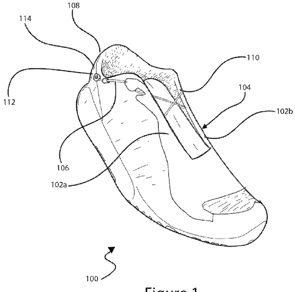
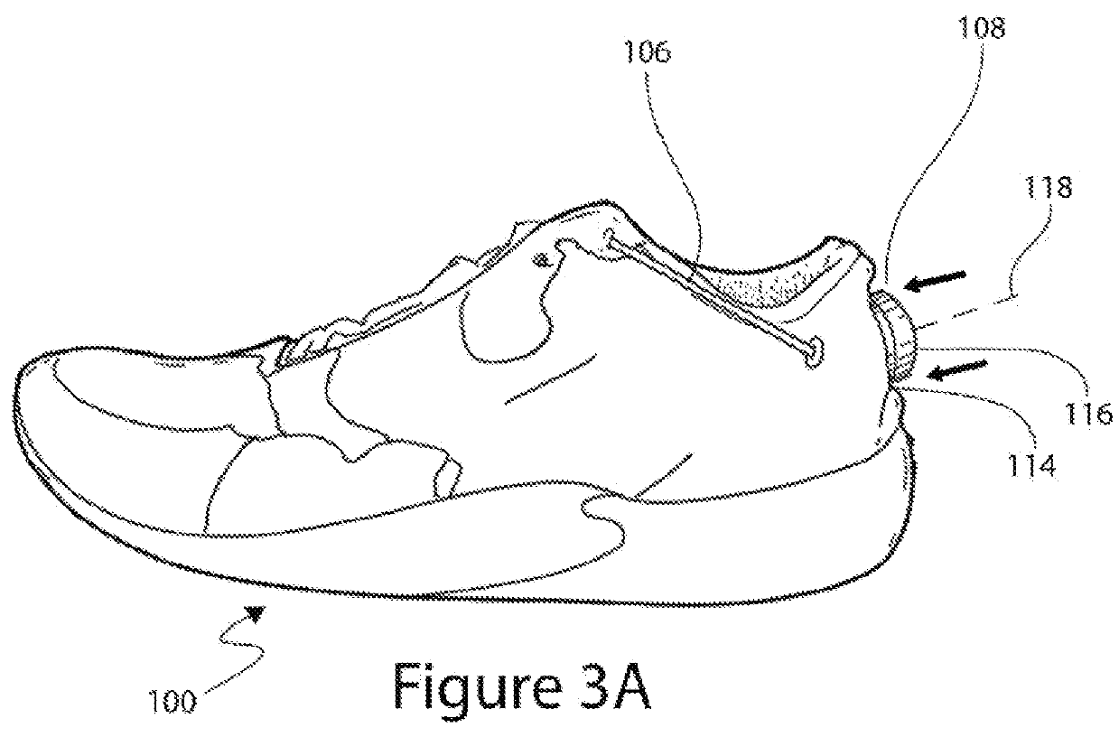
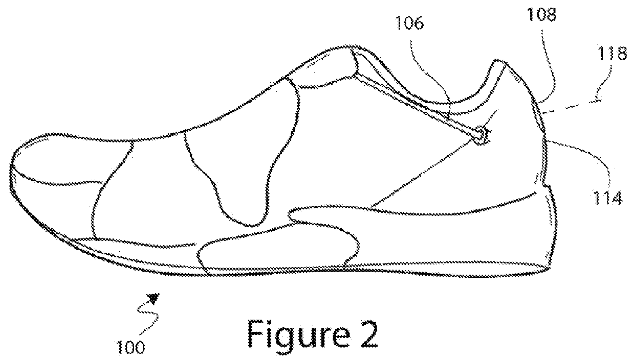
[0083]FIG. 1 is an isometric view of an example embodiment of a shoe 100 that includes a reel-based tightening system. Although many embodiments are discussed herein as relating to shoes or other footwear, the embodiments disclosed herein can also related to other types of wearable articles, and to other objects that can be tightened and / or loosened (e.g., boots, hats, belts, sandals, gloves, braces, backpacks, snowboard bindings). The shoe 100 of FIG. 1 can include a first portion 102a and a second portion 102b that can be drawn towards each other to tighten the shoe 100 and can be moved away from each other to loosen the shoe 100. The first and second portions 102a and 102b can be spaced apart forming a gap 104 therebetween, or, in some embodiments, the first and second portions 102a and 102b can touch or overlap. A tension member, such as a lace 106, can extend between the first and second portions 102a and 102b so that increased tension on the lace 106 can cause the first and se...


PUM

PropertyMeasurementUnit
thicknessesaaaaaaaaaa
radial distanceaaaaaaaaaa
compressibleaaaaaaaaaa

Abstract

This disclosure relates to articles that include a tightening mechanism, such as reel-based lace tightening mechanism, configured to tighten the article by rotation of a knob. The articles can include a concealing portion that is configured to conceal or protect at least a portion of the tightening mechanism, such as the knob. The concealing portion can be configured to prevent unintentional actuation of the tightening mechanism, such as during contact sports. The concealing portion can be configured to hide the tightening mechanism from view to improve the visual appearance of the article. The concealing portion can be collapsible such that a user can press the concealing portion down to expose the knob of the tightening mechanism.

Description

CROSS-REFERENCES TO RELATED APPLICATIONS[0001]This application claims priority to Provisional U.S. Patent Application No. 61 / 611,418 filed Mar. 15, 2012, entitled “Tightening Mechanisms and Applications Including the Same,” the entire disclosure of which is hereby incorporated by reference, for all purposes, as if fully set forth herein.BACKGROUND OF THE INVENTION[0002]1. Field of the Disclosure[0003]Some embodiments of the present disclosure relate to articles (e.g., shoes, boots, braces, and other wearable articles) that use tightening systems (e.g., lacing systems), and more particularly to articles that include a tightening mechanism that is at least partially concealed or protected.[0004]2. Description of the Related Art[0005]Although various lacing systems are available for use in connection with various wearable articles, existing lacing systems suffer from various drawbacks. For example, some lacing systems include an exposed lace tightening mechanism, which can be visually ...

Claims


Application Information

Patent Timeline
Patent Type & Authority Patents(United States)
IPC IPC(8): A43C11/00A43C19/00A43C11/20A43C11/16A43C7/08A43C1/06A41F1/00
CPCA43C11/165A43C1/06A43C7/08A43C11/20A43C19/00A41F1/00Y10T29/49599
Inventor BURNS, ROBERT EARLHAMMERSLAG, GARY R.IRWIN, ERIC CRAIGLOVETT, KRISTOPHER CARLTONNICKEL, MICHAEL JOSEPHSODERBERG, MARK STANLEY
Owner BOA TECHNOLOGY
Why Eureka
Try Eureka