
Inverter terminal board installed in motor case and packing

a technology of inverter terminals and motor cases, applied in the direction of coupling device details, coupling device connections, association with control/drive circuits, etc., can solve problems such as damage to connectors, and achieve the effects of large vibration, stable fit, and long deformation strok

Active Publication Date: 2016-07-12
YAZAKI CORP
View PDF29 Cites 7 Cited by
  • Summary
  • Abstract
  • Description
  • Claims
  • Application Information

AI Technical Summary

Benefits of technology

The solution ensures effective sealing against vibrations, maintains the connector terminal's vertical state, and compensates for relative movement between the inverter and motor, preventing damage and ensuring resource efficiency and ease of attachment.

Problems solved by technology

However, in such a configuration, a vibration phase difference between the inverter and the motor by vibration of the motor itself or vibration of a vehicle body at the time of driving is applied to the connector and the connector may be damaged.

Method used


Image

  • Inverter terminal board installed in motor case and packing
  • Inverter terminal board installed in motor case and packing
  • Inverter terminal board installed in motor case and packing

Examples


first embodiment

Inverter Terminal Board to which the Invention is Applied

[0043]First, an inverter terminal board to which the invention is applied will be described on the premise that a first embodiment of the invention is described.

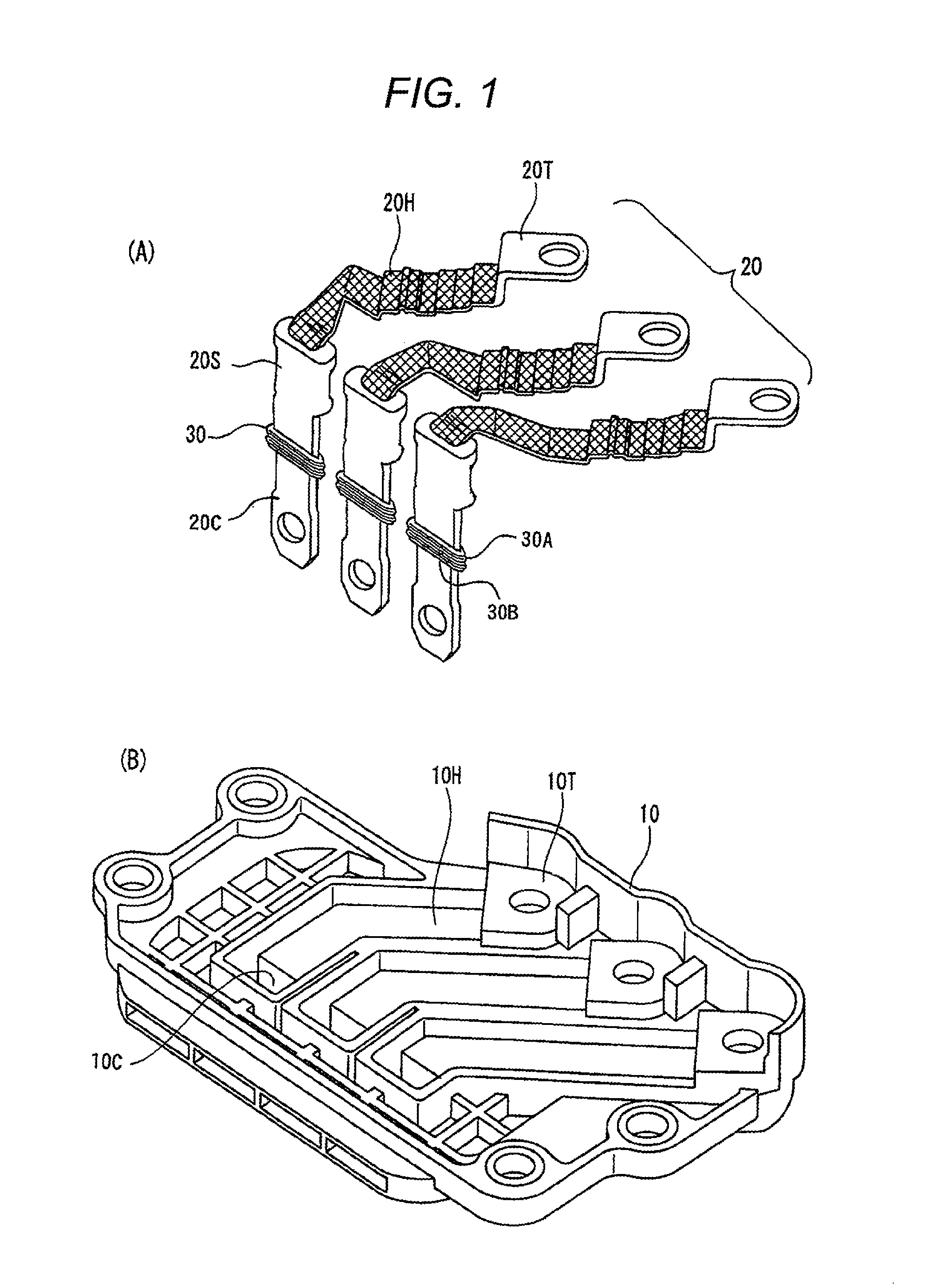
[0044]Both FIGS. 1(A) and 1(B) construct an exploded perspective view of an inverter terminal board to which the invention is applied, and FIG. 1(A) shows an electric conductor using a braid of the inverter side, and FIG. 1(B) shows the inverter terminal board for receiving the electric conductor of FIG. 1(A).

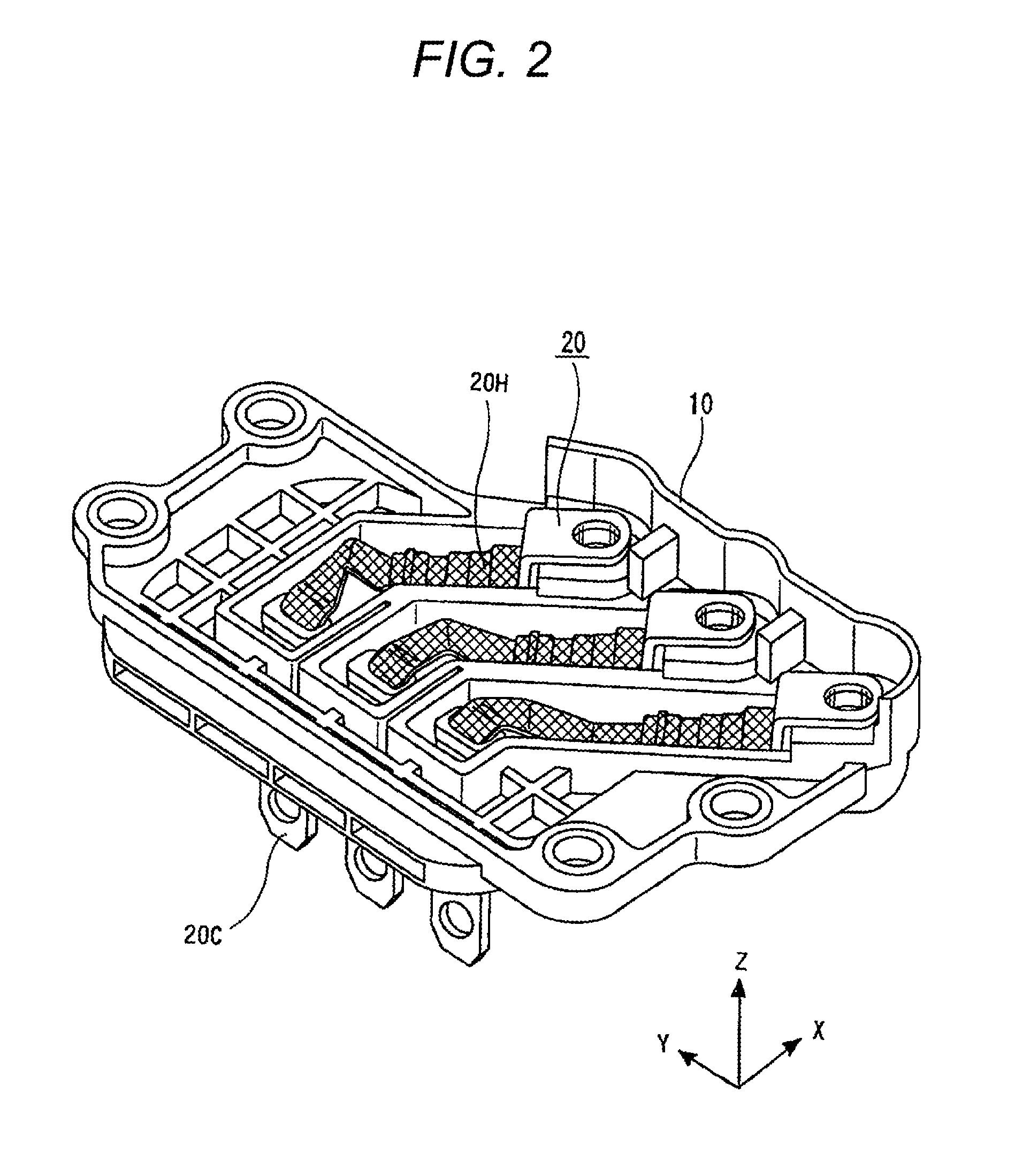
[0045]In FIG. 1(A), electric conductors 20 are the electric conductors of three systems for supplying an AC three-phase current produced in the inverter side to the motor side, and each of the electric conductors includes an inverter side connecting terminal 20T, a braid 20H whose one end is connected to the inverter side connecting terminal 20T, and a connector terminal 20C having a caulked part 20S in which the other end of the braid 20H is caulked. Since the fl...

second embodiment

[0069]A second embodiment has been implemented in order to solve such a problem of the first embodiment, and is constructed so as to provide both upper and lower ends of packing 30 with an upper spacer 40U and a lower spacer 40S by noticing that the problem described above can be solved by preventing the connector terminal 20C from being inclined as shown FIG. 7(C) even for vibration.

[0070]

[0071]FIG. 8(A) is a perspective view seen from the back side of the connector terminal 20C representing the packing 30 of the first embodiment, and FIG. 8(B) is a perspective view seen from the back side of the connector terminal 20C representing the packing 30 of the first embodiment and the upper spacer 40U and the lower spacer 40S with which both ends of the packing 30 are provided. Both of the upper spacer 40U and the lower spacer 40S have the same shape made of the same material, and have an oval shape in plan view and have the shape in which a hole through which the connector terminal 20C e...


PUM


Abstract

An inverter terminal board and packing capable of performing a packing function even when variations due to assembly tolerances of a motor and an inverter are great and large relative movement occurs between the inverter and the motor are provided. In an inverter terminal board 10 including an electric conductor 20 which has an inverter side connecting terminal 20T attached to a case of a motor and a connector terminal 20C for supplying power to a power receiving terminal of the motor and is made by connecting the connecting terminal 20T to the connector terminal 20C, the inverter terminal board in which the connector terminal 20C has a flat plate shape and packing 30 is attached over the entire periphery of the connector terminal 20C, a wall thickness of a portion abutting on a flat plate side of the flat plate-shaped terminal in the entire periphery of the packing 30 is made thicker than a wall thickness of the other portion.

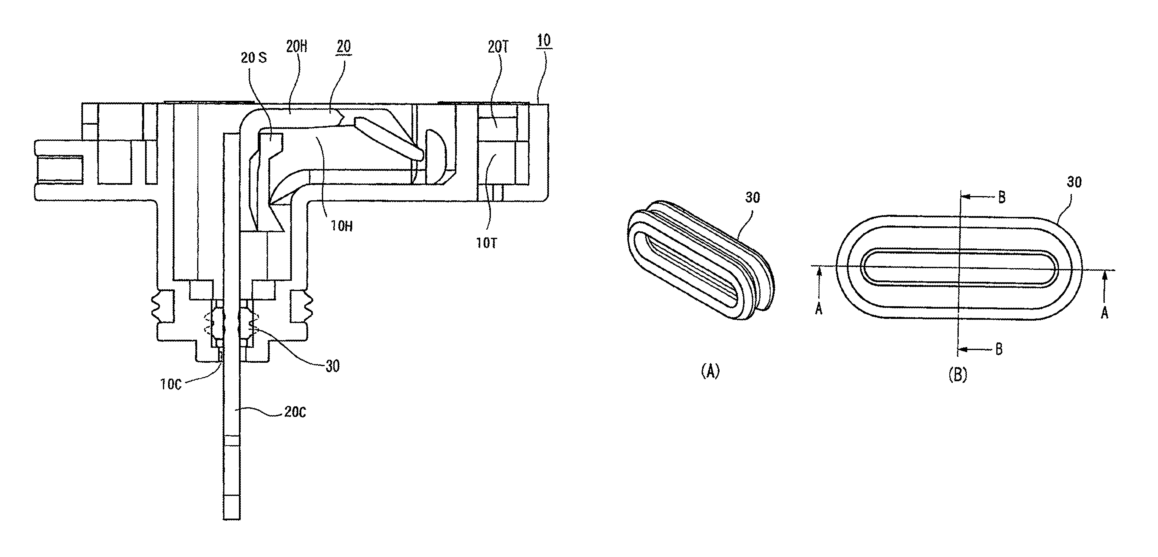
Description

TECHNICAL FIELD[0001]The present invention relates to a suitable inverter terminal board unaffected by vibration under an environment of occurrence of the vibration in the case of installing an inverter used for a vehicle etc. in a motor case, and particularly to a shape of packing used in the inverter terminal board.BACKGROUND ART[0002]An electric vehicle or a hybrid electric vehicle generally includes a motor and an inverter between a battery and wheels in order to drive the wheels by electric power accumulated in the battery.[0003]The electric power accumulated in the battery is converted by the inverter of an inverter device etc. and is supplied to the motor and rotates the motor, and rotation of the motor is transmitted to the wheels and drives the wheels.[0004]Conventionally, the inverter and the motor were mounted in separate places of the vehicle and a terminal of the inverter was connected to a terminal of the motor using a wire harness.[0005]On the other hand, a structure ...

Claims


Application Information

Patent Timeline
Patent Type & Authority Patents(United States)
IPC IPC(8): H02K11/00H01R13/52H01R9/24H02K5/22H01R11/12
CPCH02K5/225H01R9/24H01R13/521H02K11/33H01R11/12H01R2201/26H01R35/02H01R11/01
Inventor KOBAYASHI, MASAKIOKAMOTO, KENICHI
Owner YAZAKI CORP
Learn More