Inverter terminal board installed in motor case and packing
a technology of inverter terminals and motor cases, applied in the direction of coupling device details, coupling device connections, association with control/drive circuits, etc., can solve problems such as damage to connectors, and achieve the effects of large vibration, stable fit, and long deformation strok
- Summary
- Abstract
- Description
- Claims
- Application Information
AI Technical Summary
Benefits of technology
Problems solved by technology
Method used
Image
Examples
first embodiment
[0043]
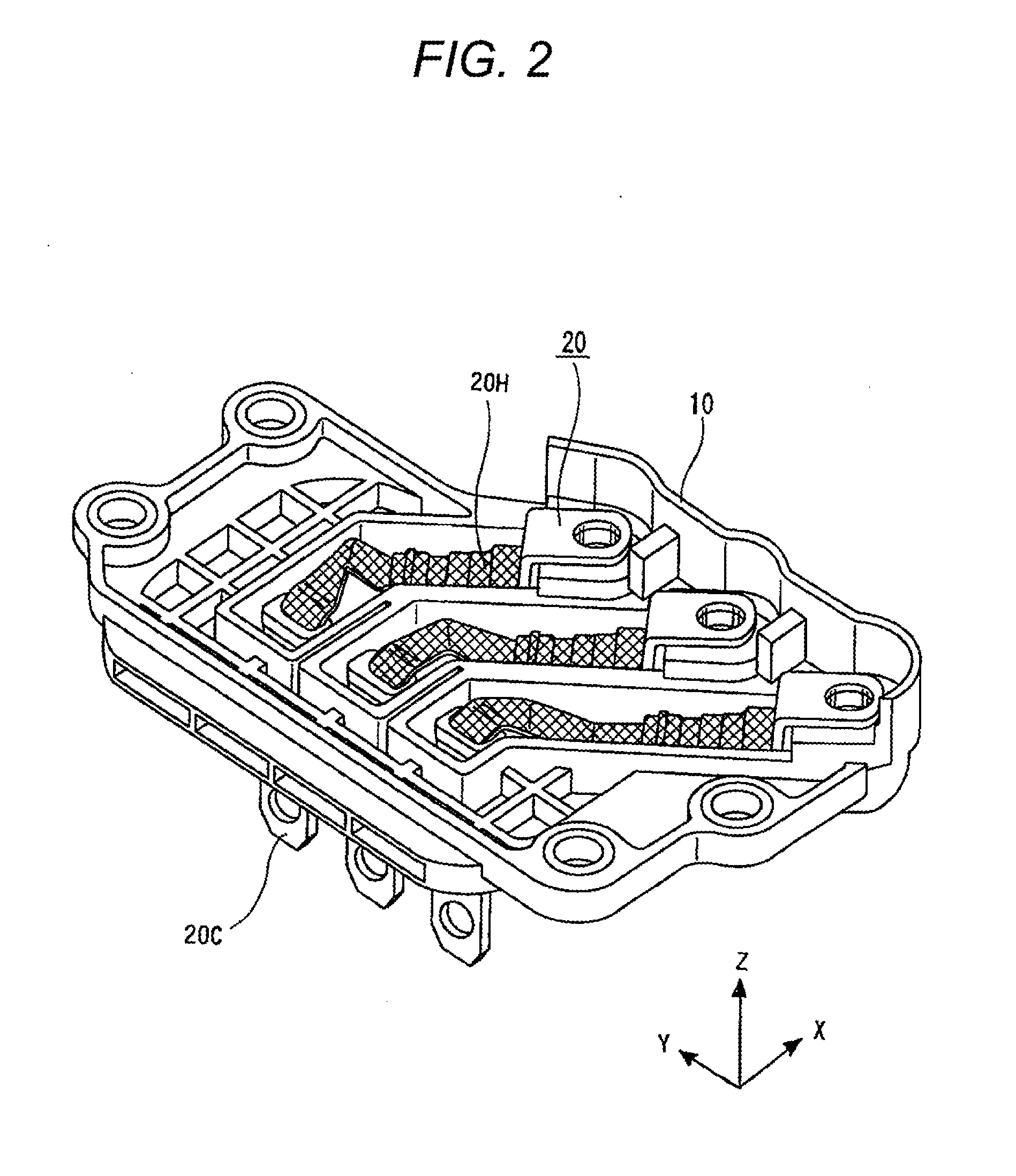
[0044]First, an inverter terminal board to which the invention is applied will be described on the premise that a first embodiment of the invention is described.
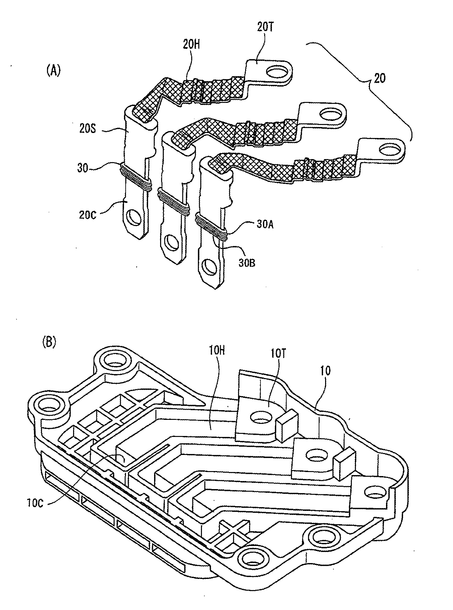
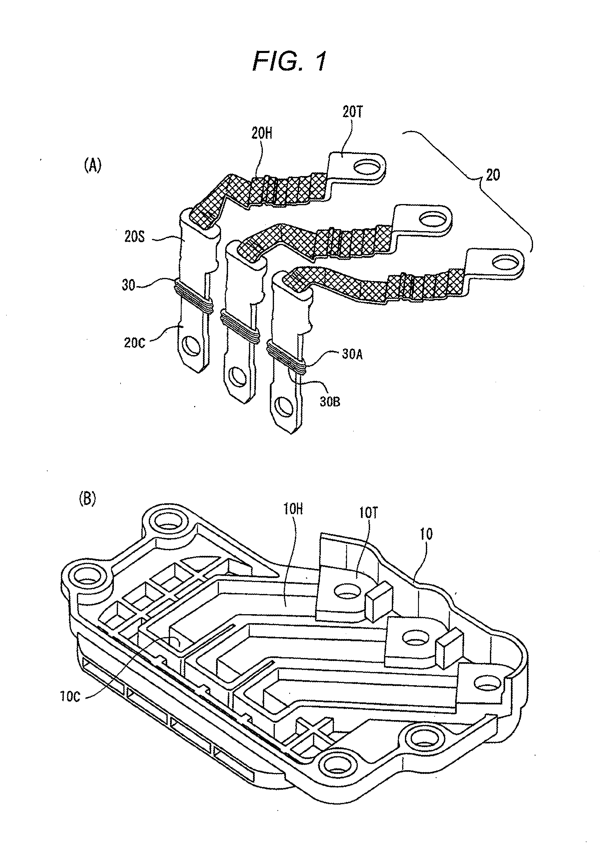
[0045]Both FIGS. 1(A) and 1(B) construct an exploded perspective view of an inverter terminal board to which the invention is applied, and FIG. 1(A) shows an electric conductor using a braid of the inverter side, and FIG. 1(B) shows the inverter terminal board for receiving the electric conductor of FIG. 1(A).
[0046]In FIG. 1(A), electric conductors 20 are the electric conductors of three systems for supplying an AC three-phase current produced in the inverter side to the motor side, and each of the electric conductors includes an inverter side connecting terminal 20T, a braid 20H whose one end is connected to the inverter side connecting terminal 20T, and a connector terminal 20C having a caulked part 20S in which the other end of the braid 20H is caulked. Since the flexible braid 20H is interposed between the inverter...
second embodiment
[0065]
[0066]As described above, a packing function is effectively fulfilled with respect to any vibration by using the packing 30 of the invention, but it was revealed that a packing leak occurs only under specific conditions. As a result of pursuing the cause, the specific conditions could be ascertained.
[0067]Hence, a problem of the packing 30 of the invention will be described using FIGS. 7(A) to 7(C).
[0068]FIGS. 7(A) to 7(C) are sectional views describing the function of the packing 30, and FIG. 7(A) shows a state of the packing 30 at the time of no vibration, and FIG. 7(B) shows a state of the packing 30 at the time when the connector terminal 20C is displaced by vibration while maintaining a vertical state, and FIG. 7(C) represents a deformed state of each packing 30 at the time when the connector terminal 20C is inclined by vibration.
[0069]At the time of no vibration of FIG. 7(A), the packing 30 is in contact with a contact surface of the entire periphery, so that the packing...
PUM
 Abstract
Description
Claims
Application Information
 - R&D
- Intellectual Property
- Life Sciences
- Materials
- Tech Scout
- Unparalleled Data Quality
- Higher Quality Content
- 60% Fewer Hallucinations
Browse by: Latest US Patents, China's latest patents, Technical Efficacy Thesaurus, Application Domain, Technology Topic, Popular Technical Reports.
© 2025 PatSnap. All rights reserved.Legal|Privacy policy|Modern Slavery Act Transparency Statement|Sitemap|About US| Contact US: help@patsnap.com


