Liquid consuming apparatus

a liquid consumption apparatus and liquid technology, applied in printing and other directions, can solve the problems of inability of known ink-jet recording apparatus to estimate the viscosity of ink stored in ink containers, so as to achieve the effect of estimating the viscosity of liquid stored in the liquid chamber

Active Publication Date: 2016-07-19
BROTHER KOGYO KK
View PDF27 Cites 0 Cited by
  • Summary
  • Abstract
  • Description
  • Claims
  • Application Information

AI Technical Summary

Benefits of technology

[0006]Therefore, a need has arisen for a liquid consuming apparatus which overcomes these and other shortcomings of the related art. A technical advantage of the present invention is that the viscosity of liquid stored in a liquid cartridge may be estimated by more direct measurement.
[0007]According to an aspect of the present invention, a liquid consuming apparatus comprises a liquid cartridge comprising: a liquid chamber configured to store liquid therein a liquid supply portion configured to supply the liquid from the liquid chamber to the outside of the liquid cartridge; an air communication portion configured to bring the liquid chamber into communication with the atmosphere outside the liquid cartridge; and a capillary portion having a first end configured to be in communication with the liquid chamber and a second end configured to be in communication with the atmosphere outside the liquid cartridge, wherein the capillary portion is configured to move the liquid from the first end to the second end therethrough by capillary force; a cartridge mounting portion configured to receive the liquid cartridge; a liquid consuming portion configured to consume the liquid supplied via the liquid supply portion from the liquid cartridge mounted to the cartridge mounting portion; a contact member provided at the cartridge mounting portion and configured to contact and move a portion of the liquid cartridge mounted to the liquid cartridge mounting portion for bringing the liquid chamber into communication with the atmosphere outside the liquid cartridge via the air communication portion; a detector configured to output a detection signal based on presence or absence of the liquid in a detection position in the capillary portion; and a controller configured to: measure, based on the detection signal output from the detector, a physical quantity, based on which a velocity of liquid moving in the capillary portion can be specified; and determine whether the physical quantity is within a threshold range.
[0008]With this configuration, the velocity of the liquid moving in the capillary portion varies depending on the viscosity of liquid in the liquid chamber. By measuring a physical quantity, based on which the velocity of the liquid can be specified, the viscosity of liquid stored in the liquid chamber may be estimated.

Problems solved by technology

Nevertheless, this known ink-jet recording apparatus does not estimate the viscosity by directly measuring a physical quantity obtained when ink moves in the ink container.
Moreover, this known ink-jet recording apparatus cannot estimate the viscosity of ink stored in an ink container which has not been mounted to the ink-jet recording apparatus and been unused.

Method used


Image

  • Liquid consuming apparatus
  • Liquid consuming apparatus
  • Liquid consuming apparatus

Examples


first modified embodiment

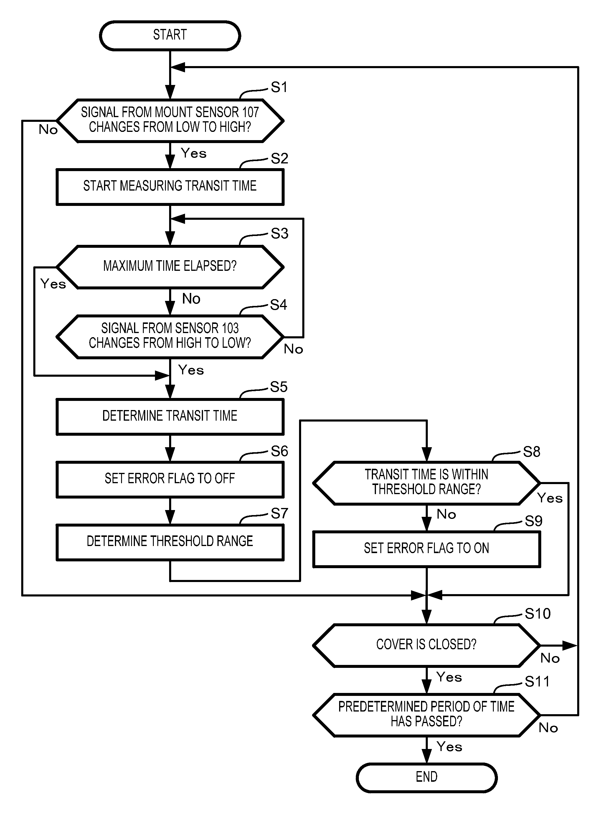
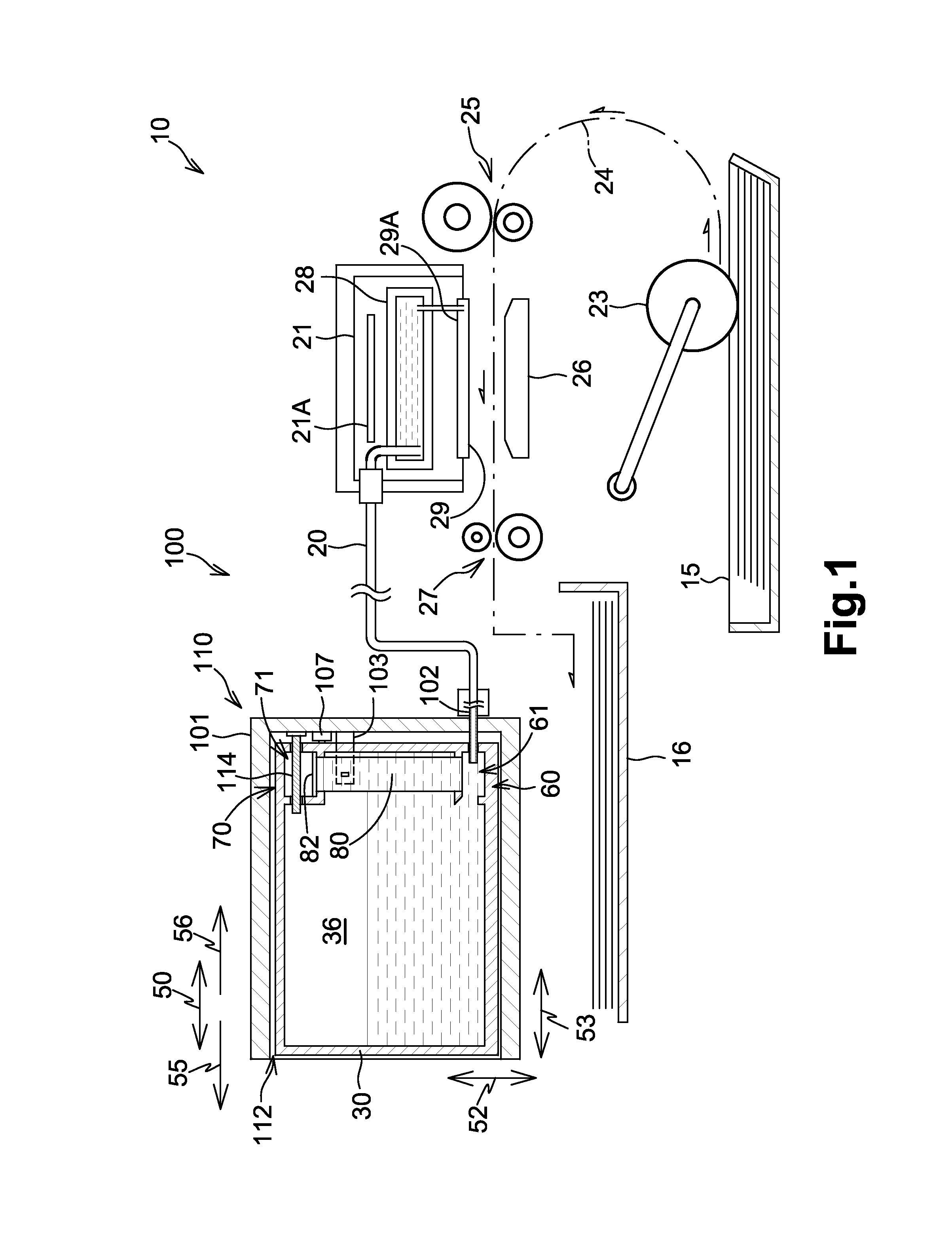
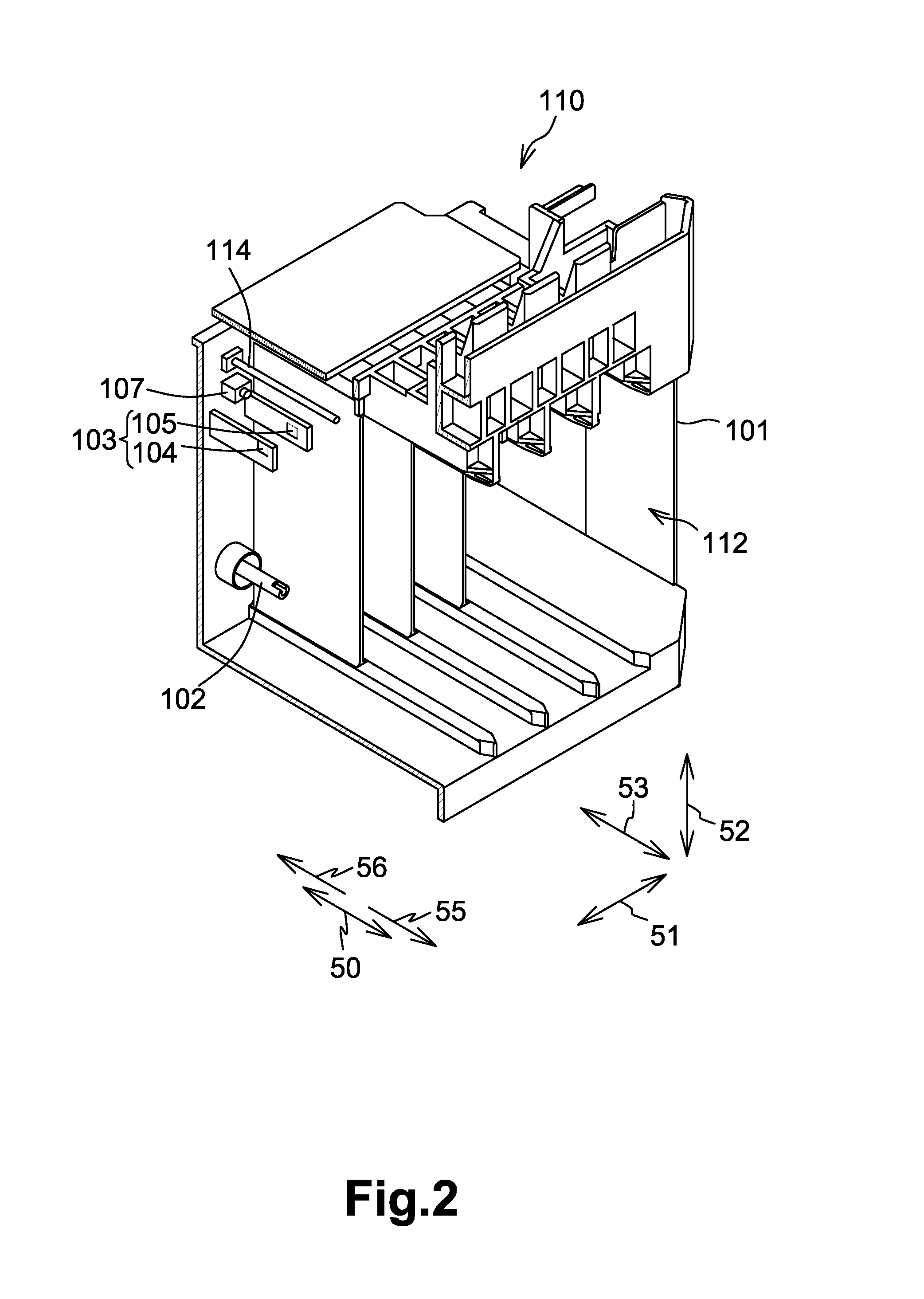
[0083]For instance, referring to FIG. 11, a cartridge mounting portion 110 comprises a first optical sensor 121 and a second optical sensor 122 positioned away from each other in the height direction 52, and the first optical sensor 121 and second optical sensor 122 face the capillary portion 80 of the ink cartridge 30 mounted to the cartridge mounting portion 110. The first optical sensor 121 and the second optical sensor 122 have the same structure as the sensor 103. The controller 130 measures, as the transit time, a time from when the ink surface in the capillary portion 80 reaches the first optical sensor 121 to when the ink surface reaches the second optical sensor 122. In this first modified embodiment, the controller 130 starts measuring the transit time after the mounting of the ink cartridge 30 to the cartridge mounting portion 110 is completed. In another embodiment, the controller 130 may start measuring the transit time just before the mounting of the ink cartridge 30 ...

second modified embodiment

[0085]For instance, referring to FIGS. 12A and 12B, an ink cartridge 30 comprises a closing member, e.g., a film 65, attached to the wall having the opening 63 formed therethrough. Before the ink cartridge 30 is mounted to the cartridge mounting portion 110, the opening 63 is closed by the film 65, such that the communication between the ink chamber 36 and the ink supply chamber 61 is blocked by the film 65. The hollow tube 102 is configured to contact the film 65 when the ink cartridge 30 is mounted to the cartridge mounting portion 110. The hollow tube 102 then ruptures the film 65. The ruptured portion of the film 65 moves to form an opening in the film 65 through which the hollow tube 102 is inserted. In other words, a portion of the film 65 is moved by the hollow tube 102. When the hollow tube 102 is inserted through the film 65 and the opening 63, the ink chamber 36 is brought into communication with the ink supply chamber 61.

[0086]The ink cartridge 30 according to this secon...


PUM


Abstract

A liquid consuming apparatus includes a liquid cartridge including a capillary portion having a first end configured to be in communication with the liquid chamber and a second end configured to be in communication with the atmosphere outside the liquid cartridge. The apparatus also includes a detector configured to output a detection signal based on the presence or absence of the liquid in a detection position in the capillary portion and a controller configured to measure, based on the detection signal output from the detector, a physical quantity, based on which a velocity of liquid moving in the capillary portion can be specified and determine whether the physical quantity is within a threshold range.

Description

CROSS-REFERENCE TO RELATED APPLICATION[0001]The present application claims priority to and the benefit of European Patent Application No. 14181446.7, which was filed on Aug. 19, 2014, the disclosure of which is incorporated herein by reference in its entirety.BACKGROUND OF THE INVENTION[0002]1. Field of the Invention[0003]The present invention relates to a liquid cartridge.[0004]2. Description of Related Art[0005]A known ink jet recording apparatus is configured to record an image on a recording medium by ejecting ink stored in an ink container from nozzles. The viscosity of ink stored in the ink container may change over time. A known ink-jet recording apparatus, as described in Patent Application Publication No. JP-09-277560 A, is configured to estimate the viscosity of ink stored in an ink container, and perform optimized preliminary ejection based on the result of the estimation. More specifically, the ink-jet recording apparatus is configured to estimate the viscosity of ink ba...

Claims


Application Information

Patent Timeline
Patent Type & Authority Patents(United States)
IPC IPC(8): B41J2/175
CPCB41J2/17566B41J2/17513
Inventor KONDO, HIROFUMIHAYASHIDA, KENTANAGANO, TAROOHISHI, AYAKOTOMOGUCHI, SUGURUSUGAHARA, HIROTO
Owner BROTHER KOGYO KK
Why Eureka
Try Eureka