Adjustable bracket device for selectively mounting rain gutters on buildings

a technology for fixing devices and buildings, applied in curtain suspension devices, roofs, constructions, etc., can solve the problems of progressive lifting and peeling of adjacent roofs and building facia components, little or no industry guidelines for wind design of gutters, and the effect of reducing the effect of wind resistan

Active Publication Date: 2016-07-19
W P HICKMAN +2
View PDF21 Cites 0 Cited by
  • Summary
  • Abstract
  • Description
  • Claims
  • Application Information

AI Technical Summary

Benefits of technology

[0008]It is also contemplated that the mounting member of the base may be formed with embossings for engagement against the back wall of the gutter to resist relative movement therebetween when secured to the vertical surface of the building.

Problems solved by technology

However, little attention may be given to the wind resistance of certain non-structural exterior building components, such as rain gutters.
Rain gutter mounting systems, typically a series of hanger brackets which support a gutter along a roof perimeter, are generally well designed to resist the expected gravitational loads imposed by rainwater runoff into the gutters but can be highly subject to wind forces acting underneath the gutter system which can tend to uplift the gutter from the building and can, in turn, result in progressive lifting and peeling of the adjacent roof and building facia components.
In the past, there has been little or no industry guidelines for wind design of gutters.

Method used


Image

  • Adjustable bracket device for selectively mounting rain gutters on buildings
  • Adjustable bracket device for selectively mounting rain gutters on buildings
  • Adjustable bracket device for selectively mounting rain gutters on buildings

Examples


Embodiment Construction

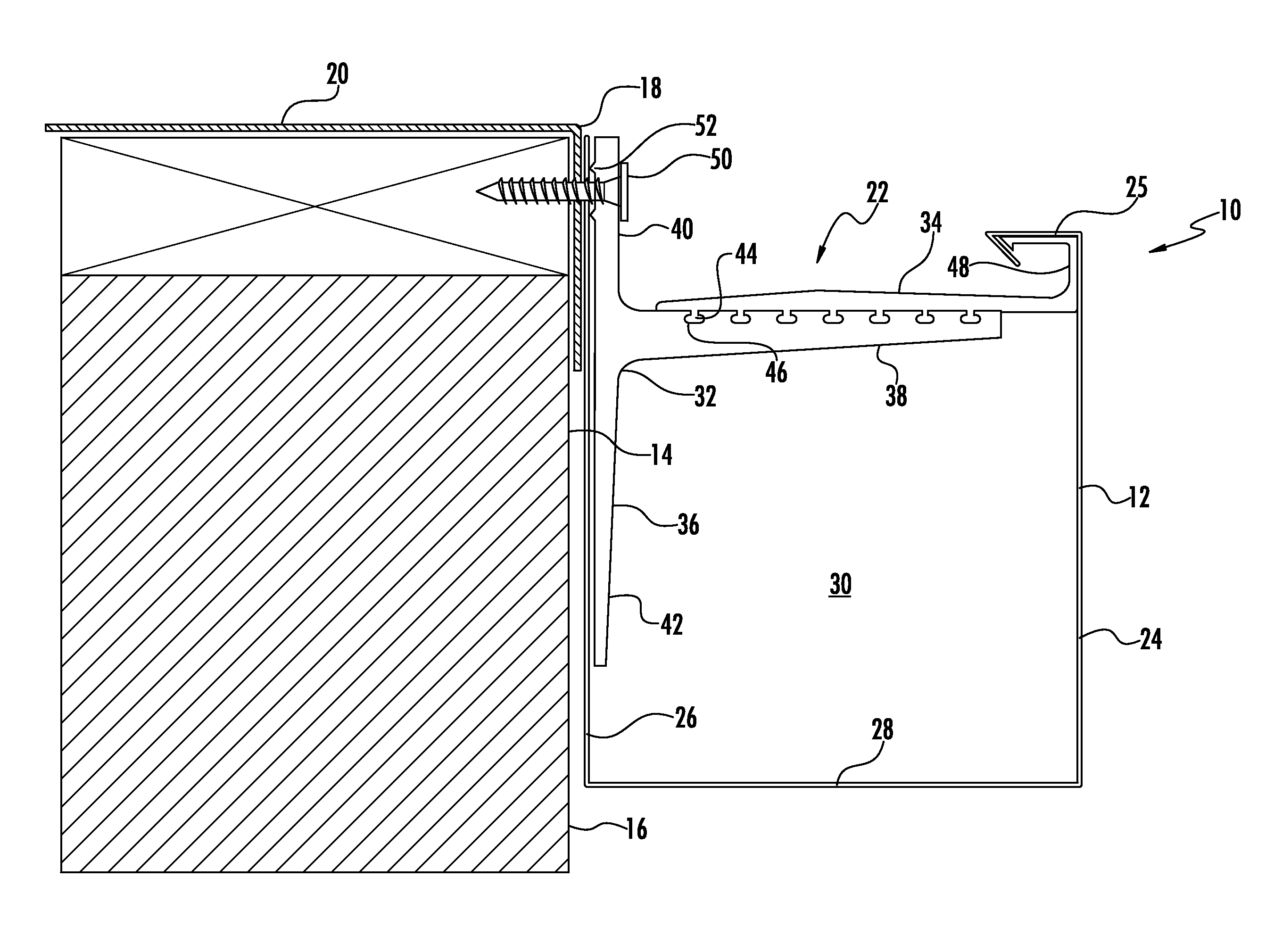
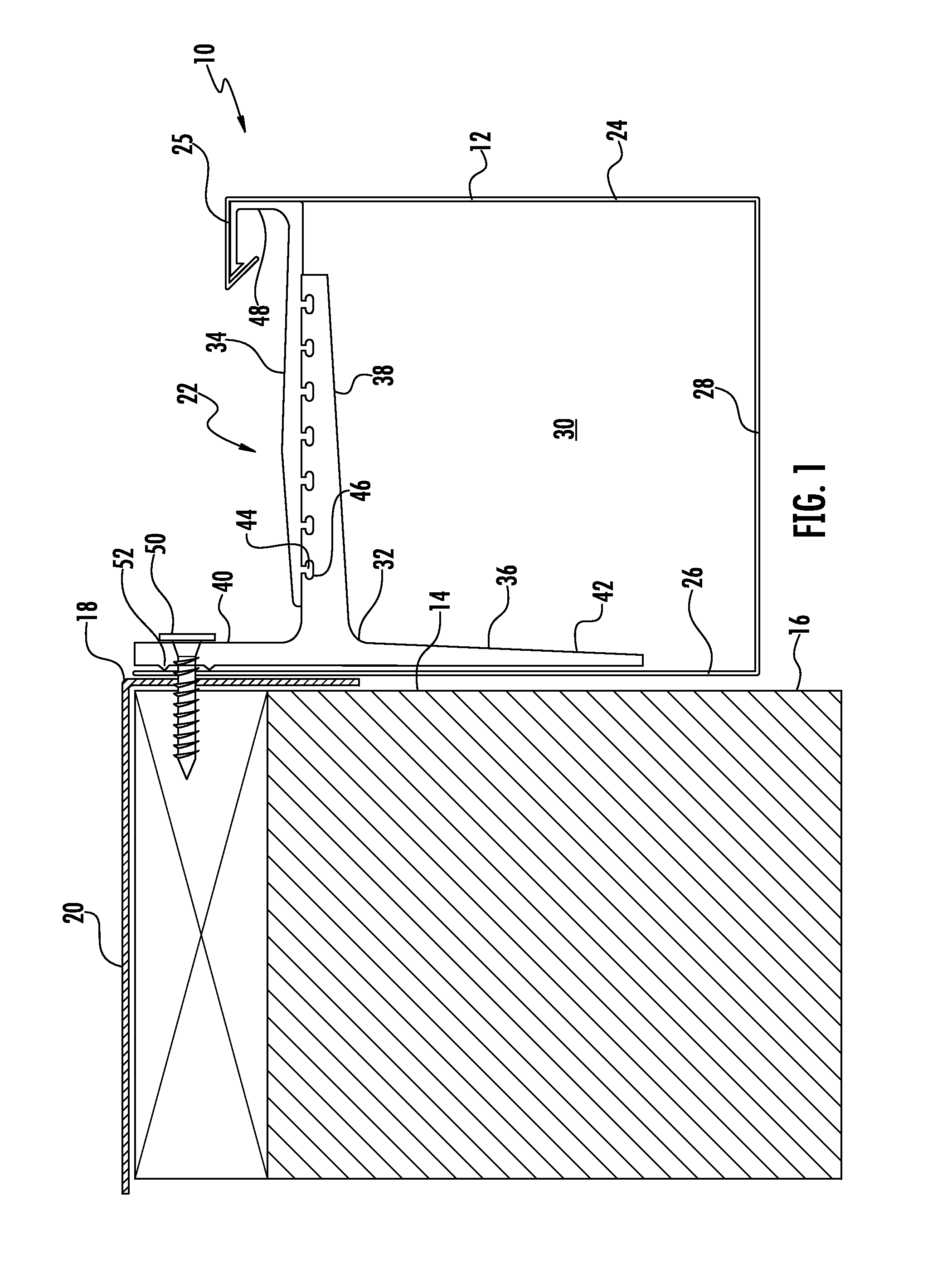
[0015]Referring now to the accompanying drawings and initially to FIG. 1, a gutter installation is depicted generally at 10 formed of a U-shaped elongate gutter 12 mounted to a vertical wall 14 of a building 16 adjacent a perimeter edge 18 of the building roof 20 by an adjustable bracket device, indicated generally at 22, in accordance with one contemplated embodiment of the present invention. As persons skilled in the relevant art will readily recognize and understand, the building 16, including the roof 20 and the vertical wall 14, are only generically depicted for sake of providing a simplified illustration of a representative gutter installation according to the present invention, but the present invention is not to be construed in any way as limited to use with the depicted form of building structure and, instead, it is to be expressly understood that the present invention may be adapted in the same and various other embodiments for use in substantially any form of building str...


PUM


Abstract

An adjustable bracket device for selectively mounting on buildings a plurality of rain gutters of different sizes and shapes, includes a base having an elongate mounting member and an integral arm member projecting outwardly therefrom. An extension member is attachable to the arm member in multiple overlapping relationships forming the assembled arm and extension members of differing collective lengths. The base is disposed within a selected gutter in a substantially vertical orientation with the mounting member abutted against the back wall of the gutter and is secured to a vertical building wall via a fastener penetrated through mounting member and through the back wall of the gutter. The collective overlapping length of the arm and extension members is selected to conform to the width of the selected gutter to extend laterally across the full channel width of the gutter into supporting engagement with the front wall of the gutter.

Description

FIELD OF THE INVENTION[0001]The present invention relates generally to building construction and, more particularly, to the installation of rain gutters on buildings.BACKGROUND OF THE INVENTION[0002]Architects and engineers typically give careful attention in the design of buildings, particularly commercial buildings, to the ability of the structure to safely withstand major wind events. However, little attention may be given to the wind resistance of certain non-structural exterior building components, such as rain gutters. Rain gutter mounting systems, typically a series of hanger brackets which support a gutter along a roof perimeter, are generally well designed to resist the expected gravitational loads imposed by rainwater runoff into the gutters but can be highly subject to wind forces acting underneath the gutter system which can tend to uplift the gutter from the building and can, in turn, result in progressive lifting and peeling of the adjacent roof and building facia comp...

Claims


Application Information

Patent Timeline
Patent Type & Authority Patents(United States)
IPC IPC(8): E04D13/072A47H1/144
CPCE04D13/0725A47H1/144
Inventor LECLARE, ROBERT DONALDDEMCHAK, ADAM ARDERYCAGLE, STACY DEWAYNEWEBB, WILLIAM CECILSIDDALL, MATTHEW WAYNEMCCOY, CHRISTOPHER KELLY
Owner W P HICKMAN
Why Eureka
Try Eureka