Adjustable Scooping Device

a scooping device and adjustable technology, applied in the field of scoops, can solve the problems of not being as simple and quick to use, and achieve the effects of providing sufficient flexibility, providing resistance to the movement of the bump over the teeth, and providing sufficient flexibility

Active Publication Date: 2020-06-18
RIVERA ADRIAN
View PDF4 Cites 1 Cited by
  • Summary
  • Abstract
  • Description
  • Claims
  • Application Information

AI Technical Summary

Benefits of technology

[0010]The plunger can be cylindrical, having an outer wall corresponding to the cylindrical interior sidewall of the scoop body. The outer wall of the plunger can include an annular groove. The first engagement element can be, for example, a spiral groove formed in the outer wall of the plunger, and the second engagement element can include a flap formed at the open bottom of the scoop body, and a bump formed on the flap. The plunger can also include a plurality of teeth arranged in the spiral groove and raised to an extent so as to provide resistance to movement of the bump over the teeth, and the flap provides sufficient flexibility to allow movement of the bump over the teeth. The scoop body can include a plurality of index lines marked at spaced intervals, and the plunger can include a pointer that aligns generally with a selected one of the index lines as the plunger is rotated in the hollow interior of the scoop body. Locations of the index lines can correspond to locations of the teeth. The spiral groove can terminate at one end at a bottom edge of the plunger.
[0011]The first engagement element can be multiple spiral grooves, such as first and second spiral grooves formed in the outer wall of the plunger. In this case, the second engagement element can include a flap formed at the open bottom of the scoop body, a bump formed on the flap, and a tab extending from the interior sidewall of the scoop body. The flap can be arranged, for example, opposite the tab. The bump can be configured to engage the first spiral groove, and the tab can be configured to engage the second spiral groove. The plunger can also include a plurality of teeth arranged in the spiral groove and raised to an extent so as to provide resistance to movement of the bump over the teeth, the flap can provide sufficient flexibility to allow movement of the bump over the teeth, and the tab can extend from the interior sidewall of the scoop body an insufficient distance to contact the teeth. The first and second spiral grooves can terminate at one end at a bottom edge of the plunger.

Problems solved by technology

A large scoop having markings for measuring various fractions of the entire scoop amount allows a single scoop to be used to measure different amounts, but requires careful scooping, or pouring of the material into the scoop, to avoid under- or over-measuring, and is overall not as simple and quick to use as a simple scoop.

Method used


Image

  • Adjustable Scooping Device
  • Adjustable Scooping Device
  • Adjustable Scooping Device

Examples


Embodiment Construction

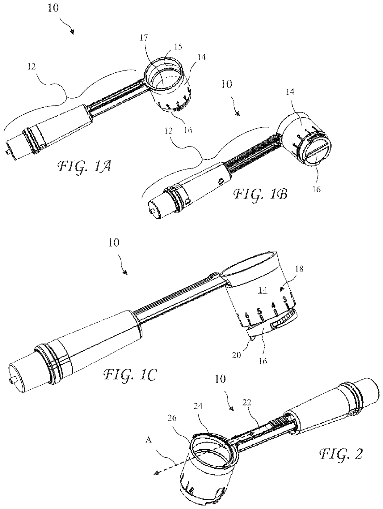
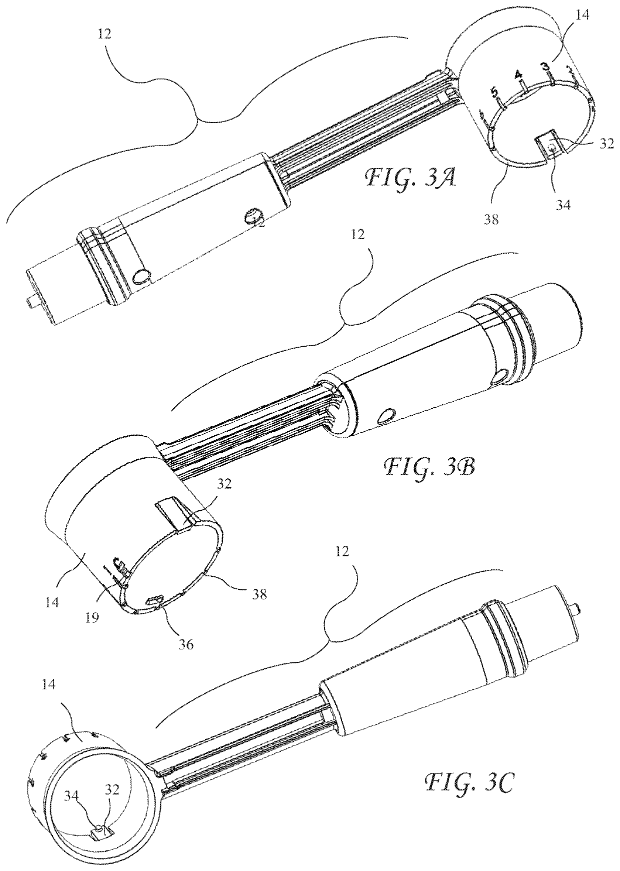
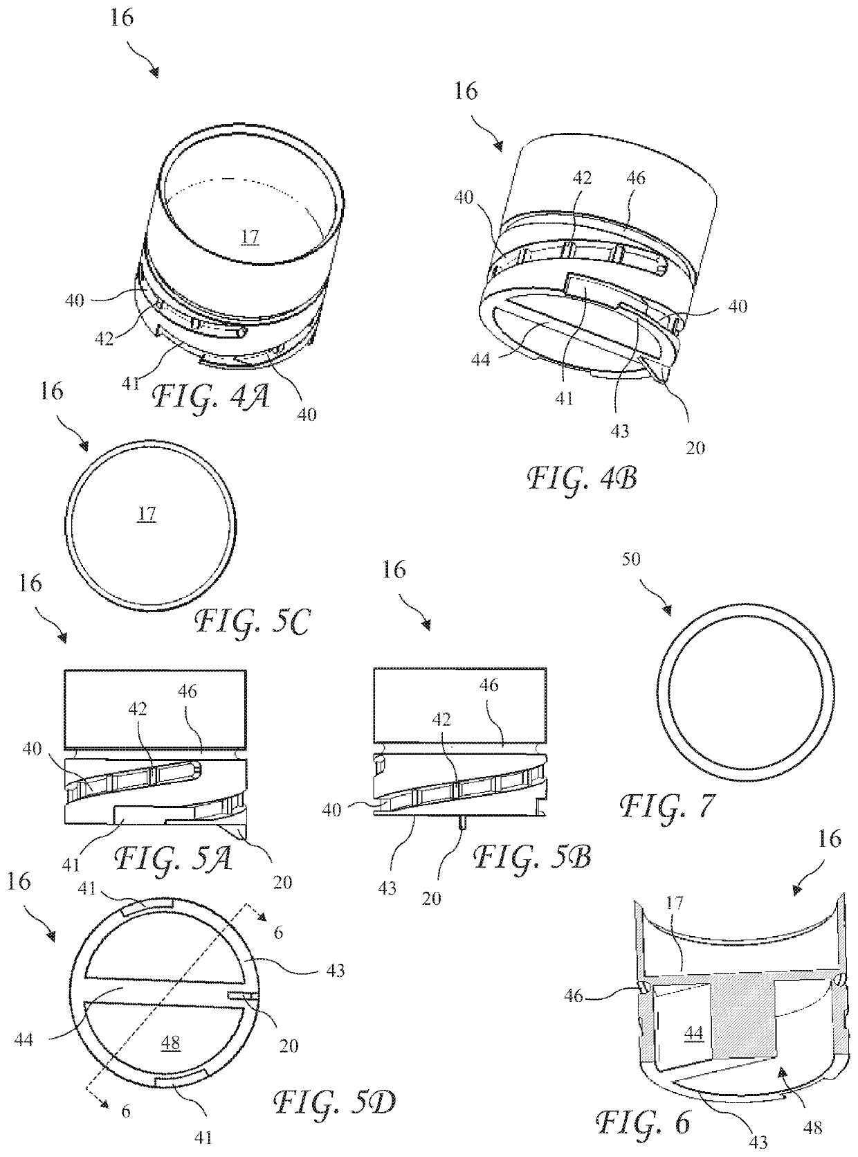
[0029]With reference to FIGS. 1A-C, an adjustable scooping device 10 includes a handle 12 and a scoop, which includes a scoop body 14 attached or integrally formed at one end of the handle 12. As shown, the scoop body 14 has a cylindrical interior 15. The scoop also includes a cylindrical plunger 16 that is movable inside the cylindrical interior 15 of the scoop body 14 to raise and lower a floor 17 of the scoop to adjust the volume of the scoop. A pointer 20 on the plunger 16 is movable to align with index lines 18 on the scoop body 14 as the plunger 16 is adjusted to indicate the volume of the scoop as the volume is adjusted. Although the scoop body 14 as shown is cylindrical with a round interior cross-section, the scoop body 14 can have any internal cross-sectional shape, as can the plunger 16. For advantageous operation, the sidewalls of the interior of the scoop body 14 should be mutually parallel, and should closely correspond to the periphery of the plunger 16.

[0030]The adju...


PUM


Abstract

An adjustable scoop includes a scoop body and a plunger. The scoop body has a cylindrical interior sidewall, a hollow interior, an open top, and an open bottom. The plunger is arranged in the interior of the scoop body such that a top surface of the plunger faces the open top. A volume of the interior of the scoop body above the plunger defines a volume of the adjustable scoop. The plunger is rotatable in the interior of the scoop body to adjust the volume of the adjustable scoop. The plunger includes a first engagement element, and a surface of the interior sidewall of the scoop body includes a second engagement element extending from the surface. The first and second engagement elements mutually cooperate to translate rotation of the plunger to adjustment of the volume of the adjustable scoop.

Description

CROSS-REFERENCE TO RELATED APPLICATION[0001]This is a continuation-in-part of co-pending U.S. patent application Ser. No. 15 / 702,695, which was filed on Sep. 12, 2017, the entire disclosure of which is incorporated herein by this reference.FIELD OF THE INVENTION[0002]The invention relates to scoops used to measure a volume of pourable substances.BACKGROUND OF THE INVENTION[0003]Cooks and bakers use various volumes of different materials when preparing food and drinks. Measuring out these volumes typically requires a number of scooping implements to measure the various different volumes. As a result, any cooking process typically requires providing, using, and cleaning a number of different measuring scoops.[0004]There are other examples of applications in which more than one measuring scoop is required due to different volumes needing to be measured. For example, brewed beverages are often prepared from measured amounts of brewing material, scooped from a bulk amount of the brewing ...

Claims


Application Information

Patent Timeline
Patent Type & Authority Applications(United States)
IPC IPC(8): G01F19/00
CPCG01F19/002G01F19/00
Inventor RIVERA, ADRIAN
Owner RIVERA ADRIAN
Why Eureka
Try Eureka