Fluid seal for endoscope

a technology of endoscopy and fluid seal, which is applied in the field of endoscopy systems and procedures, can solve the problems of fluid (bile liquid and air) leakage, inability or relative difficulty to effectively seal around the non-circular shaft, and ineffective sealing of catheters having non-circular shafts. it can effectively inhibit the egress of fluid, effectively inhibit the effect of egress

Inactive Publication Date: 2005-03-08
SCI MED LIFE SYST
View PDF39 Cites 73 Cited by
  • Summary
  • Abstract
  • Description
  • Claims
  • Application Information

AI Technical Summary

Benefits of technology

The present invention satisfies this demand by providing an endoscope seal that effectively inhibits the egress of fluid from the working channel of an endoscope when an elongate device, such as a rapid exchange biliary catheter, having a non-circular shaft is disposed therein. The seal of the present invention is also suitable for other catheters having non-circular shafts such as rapid exchange vascular catheters. In addition, some embodiments of the present invention are perfectly suitable for sealing about elongate devices having shafts with a circular profile. Accordingly, the endoscope seals of the present invention are both versatile and functional, because they effectively inhibit, or at least reduce, the egress of fluids (bile and air) from the working channel of the endoscope when an elongate device having a circular or non-circular shaft is utilized.
The endoscope seals of the present invention include a body portion having a proximal end adapted for insertion of an elongate device such as a rapid exchange type catheter, a distal end adapted for connection to the proximal end of an endoscope, a lumen extending therethrough which is adapted to receive the elongate device and to provide access to the working channel of the endoscope, and a means for conforming to the non-circular shaft of the elongate device to inhibit the flow of fluid from the working channel of the endoscope.
In a first embodiment, the conforming means may comprise a protrusion extending radially inward in the lumen of the body portion. The protrusion may comprise a geometry that mates with the non-circular shaft of the elongate device. In a second embodiment, the conforming means may comprise a plurality of protrusions extending radially inward in the lumen body portion. The plurality of protrusions may be uniformly spaced about the circumference of the lumen and may have sufficient flexibility to conform to a non-circular geometry. In a third embodiment, the conforming means may comprise a sealing material such as a surgical foam that is disposed in the lumen of the body portion or injected therein just prior to use. In a fourth embodiment, the conforming means may comprise a sealing mandrel that it is disposed in the lumen of the body portion. The sealing mandrel conforms to the non-circular geometry to define a collective circular geometry that is readily sealed by a conventional circular aperture in the body portion. Whether a single protrusion, a plurality of protrusions, a sealing material or a sealing mandrel, the present invention provides endoscope seals that readily seal about an elongate devices having either circular or non-circular profiles.

Problems solved by technology

One drawback with such rapid exchange or single operator exchange biliary catheters is the inability or relative difficulty in sealing around the non-circular shaft, such that fluid (bile liquid and air) may leak out of the working channel of the endoscope around the non-circular shaft of the biliary catheter.
Conventional endoscope seals are adapted to seal about catheters having circular shafts, and generally do not effectively seal about catheters having non-circular shafts.
Accordingly, such prior art endoscope seals do not effectively inhibit the egress of bile liquids and air exiting the working channel of the endoscope when an elongate device having a non-circular cross-section is utilized.

Method used


Image

  • Fluid seal for endoscope
  • Fluid seal for endoscope
  • Fluid seal for endoscope

Examples


Embodiment Construction

The following detailed description should be read with reference to the drawings in which similar elements and different drawings are numbered the same. The drawings, which are not necessarily to scale, depict illustrative embodiments and are not intended to limit the scope of the invention.

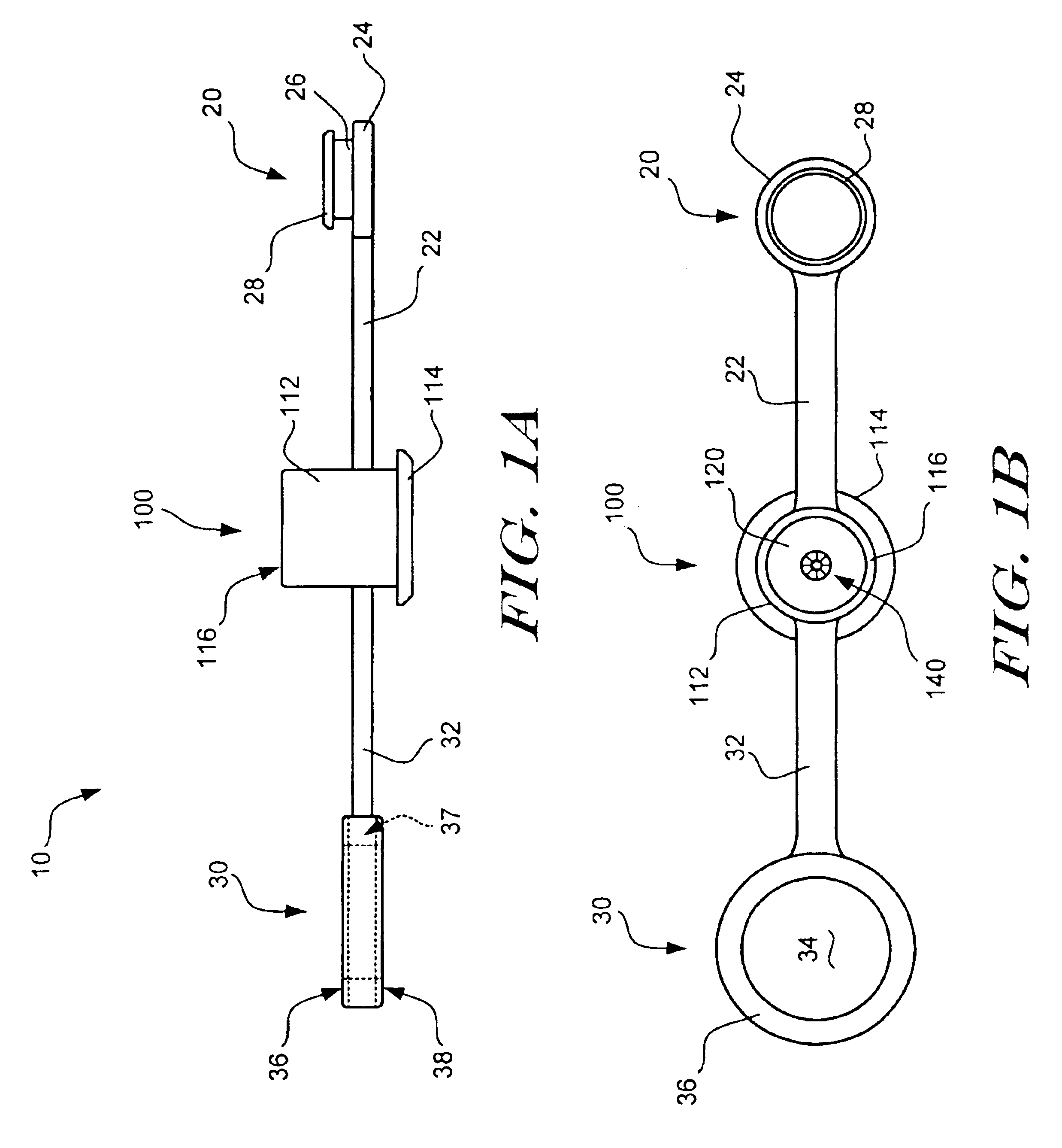
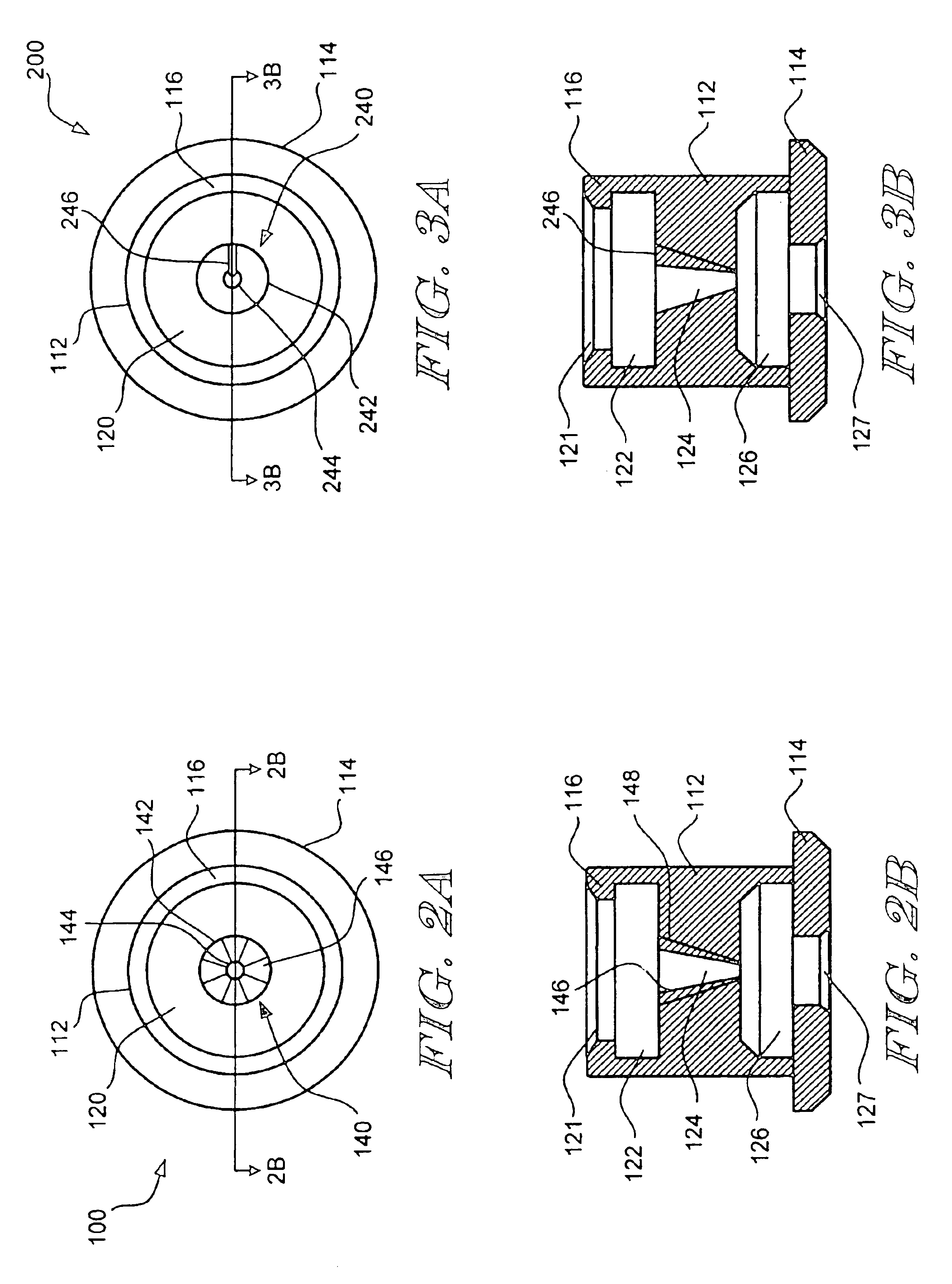
Refer now to FIG. 1A which illustrates a side view of an endoscope seal in accordance with the present invention. Endoscope seal 10 includes a main body portion 100, a plus portion 20 and an adapter ring portion 30. The details of main body portion 100 are discussed in more detail with reference to FIGS. 2A and 2B. Main body portions 200, 300, 400, and 500 as discussed in detail with reference FIGS. 3A-3B, FIGS. 4A-4B, FIGS. 5A-5B, and FIG. 6D, respectively, may be used in place of main body portion 100.

Main body portion 100 includes a body 112 having a proximal end and a distal end. An outwardly extending flange 114 is connected to the distal end of the body 112. An inwardly extending flange 116...


PUM


Abstract

An endoscope seal that effectively inhibits the egress of fluids from the working channel of an endoscope when an elongate device having a non-circular shaft is disposed therein. The endoscope seal includes a body portion having a proximal end adapted for insertion of an elongate device such as a rapid exchange biliary catheter, a distal end adapted for connection to the proximal end of an endoscope, a lumen extending therethrough which is adapted to receive the elongate device and to provide access to the working channel of the endoscope, and a means for conforming to the non-circular shaft of the elongate device to inhibit the flow of fluid from the working channel of the endoscope. The conforming means may, for example, comprise one or more protrusions extending radially inward in the lumen of the body portion, a sealing material such as a surgical foam that is disposed in the lumen of the body portion, or a sealing mandrel. Whether a single protrusion, a plurality of protrusions, a sealing material or a sealing mandrel is utilized, the present invention provides endoscope seals that readily seal about elongate devices having either circular or non-circular profiles.

Description

FIELD OF THE INVENTIONThe present invention general relates to endoscopic systems and procedures. More specifically, the present invention relates to seals for use in combination with an endoscope, sometimes referred to as endoscope seals or biopsy seals.BACKGROUND OF THE INVENTIONEndoscopic procedures for treating abnormal pathologies within the alimentary canal system and biliary tree (including the biliary, hepatic, and pancreatic ducts) are increasing in number. The endoscope provides access to the general area of a desired duct using direct visualization. However, the duct itself must be navigated using a catheter in conjunction with a guidewire under fluoroscopy. A wide variety of catheters are known for treatment of such targeted anatomical regions. Examples of biliary catheters are disclosed in U.S. Pat. No. 5,397,302 to Weaver et al., U.S. Pat. No. 5,320,602 to Karpiel and U.S. Pat. No. 5,921,971 to Argo et al., the disclosures of which are hereby incorporated by reference....

Claims


Application Information

Patent Timeline
Patent Type & Authority Patents(United States)
IPC IPC(8): A61B17/34A61B1/012A61B1/018A61B1/00G02B23/24
CPCA61B1/00137A61B1/018A61M39/04A61B17/3462A61B17/3498A61B2017/3437Y10T292/48
Inventor CARRILLO, JR., OSCAR R.HOLMES, JOHNRICHARDSON, KEVIN
Owner SCI MED LIFE SYST
Why Eureka
Try Eureka