
Embolic filtering devices

a filter device and emboli technology, applied in the field of emboli filtering devices, can solve the problems of affecting the patient's health, affecting the patient's treatment, and releasing emboli into the circulatory system can be extremely dangerous and sometimes fatal, and achieve the effects of high flexibility, sufficient strength, and sufficient flexibility

Inactive Publication Date: 2007-08-07
ABBOTT CARDIOVASCULAR
View PDF765 Cites 72 Cited by
  • Summary
  • Abstract
  • Description
  • Claims
  • Application Information

AI Technical Summary

Benefits of technology

[0015]The present invention provides a highly flexible self-expanding frame for use with an embolic filtering device designed to capture embolic debris created during the performance of a therapeutic interventional procedure, such as a balloon angioplasty or stenting procedure, in a body vessel. The present invention provides the physician with an embolic filtering device which is highly flexible to be steered through tortuous anatomy, but yet possesses sufficient strength to hold open a filtering element against the wall of the body vessel for capturing embolic debris. Moreover, the present invention provides sufficient flexibility without compromising the radiopacity characteristics of the filtering device. An embolic filtering device made in accordance with the present invention is relatively easy to deploy and has good flexibility and conformability to the patient's anatomy.
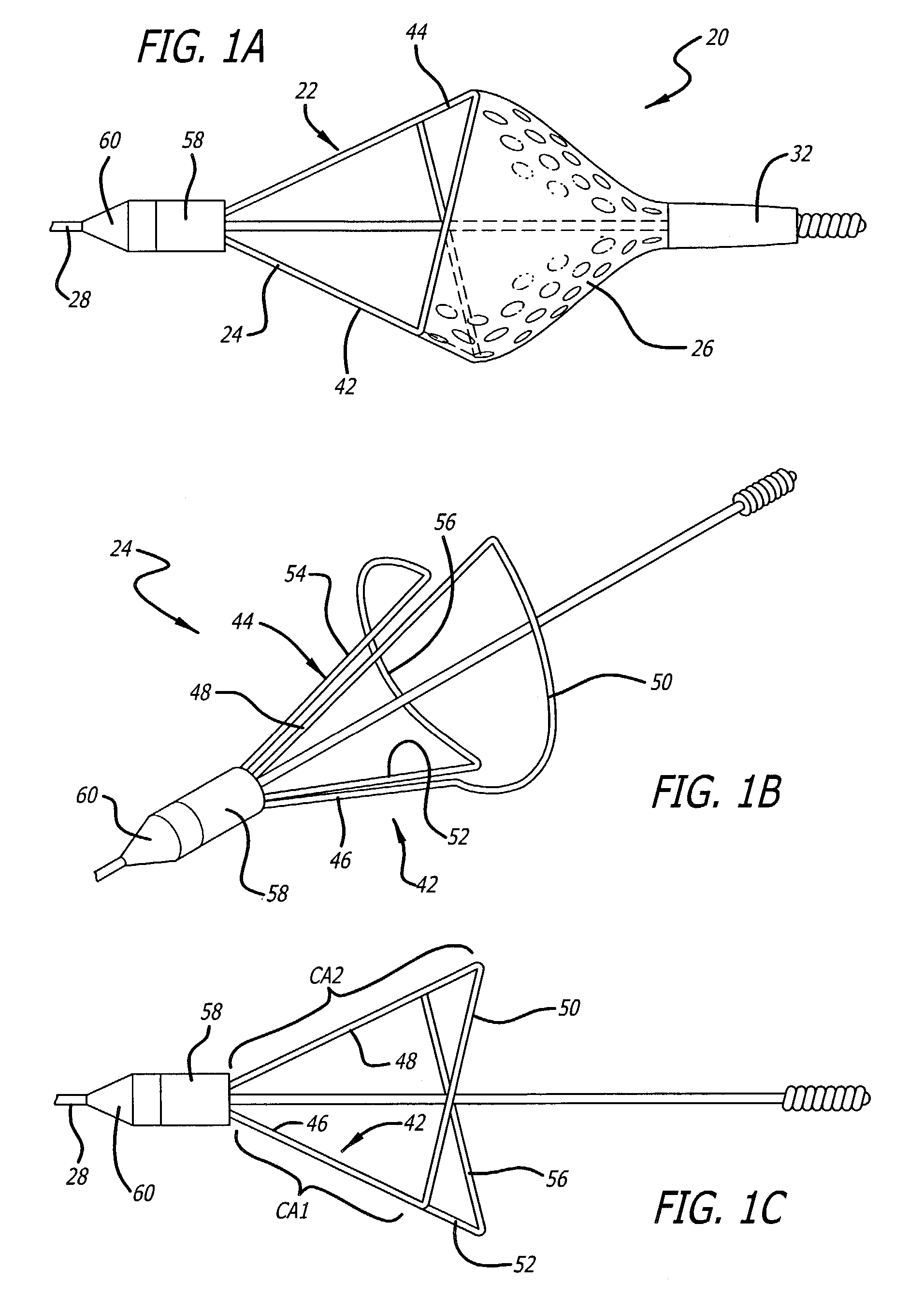
[0018]The features of the present invention are primarily directed to the pair of half frames which cooperatively form the expandable frame of the embolic filter assembly. In one aspect of the present invention, the first half frame includes a first control arm connected to a second control arm by a partial loop. The second half frame also includes a first arm connected to a second control arm via a partial loop. The partial loops of this first and second half frames cooperate to form a composite loop to which the filter element can be attached. The partial loops extend radially outward when placed in an expanded position so that a substantially circular loop is created by the two partial loops. In aspect of the present invention, the first control arm of the first half frame has a length which is smaller than the second control arm of the same half frame. Additionally, the length of the first control arm of the second half frame can be smaller than the second control arm of the second half frame. The use of different sized control arms to form each of the first and second half frames creates an offset geometry in the composite loop which can be beneficial when the filter assembly is placed in small diameter body vessels or when deployed on a curved section of a body vessel.
[0019]In another aspect of the present invention, the first and second control arms of the first half frame are disposed distally of the composite loop formed by the partial loops. The first and second arms of the second half frame are, in turn, disposed proximally of the composite loop to create diametrically opposed control arms. A third control arm which extends from the partial loop formed on the first half frame is disposed proximally of the composite loop to provide a means for collapsing the first half frame after the half frames have been deployed. This third control arm is designed to contact the distal end of a recovery sheath which is designed to contact the proximally located control arms to cause the half frames to move into the collapsed position for retrieval into the lumen of the recovery sheath. Thereafter, the recovery sheath and filter assembly can be withdrawn from the body vessel.
[0020]In another aspect of the present invention, each of the partial loops of the first and second half frames have a particular, circular shaped arc when placed in the expanded position. The arc is generally measured between the point of attachment of the first control arm and the partial loop and the point attachment of the second control arm and the partial loop. In a specific aspect of the present invention, one of the partial loops has a smaller circular-shaped arc than the other partial loop. This allows the smaller circular-shaped arc of the partial loop to move inside the other half frame in that the event the device is placed in an undersized body vessel. As a result, the partial loops of each of the half frames still cooperatively form a circular composite loop which maintains the filter element in contact with the wall of the body vessel. In this manner, the partial loops compensate and readily adapt to the smaller sized vessel.
[0022]In still other aspects of the present invention, the size of the control arms of one of the half frames can be larger than the length of the control arms of a second half frame. Additionally, the radius of the partial loop of one of the half frames can be different than the radius of the corresponding half frame. As a result, the composite expandable frame can prove to provide beneficial deployment characteristics when implanted, for example, on a curved portion of a body vessel.
[0023]The present invention is directed as well to a composite frame formed from two half frames that are attached to a tubular structure that is rotatably mounted to the guide wire. The use of a tubular structure with the half frame design provides a durable embolic filtering assembly that can be rotatably mounted onto a steerable guide wire and will rotate or spin relative to the guide wire once implanted in the body vessel. Such a tubular structure could be utilized in accordance with any of the embodiments shown and described herein.

Problems solved by technology

However, there is one common problem which can become associated with all of these non-surgical procedures, namely, the potential release of embolic debris into the bloodstream that can occlude distal vasculature and cause significant health problems to the patient.
Additionally, while complete vaporization of plaque is the intended goal during laser angioplasty, sometimes particles are not fully vaporized and enter the bloodstream.
When any of the above-described procedures are performed in the carotid arteries, the release of emboli into the circulatory system can be extremely dangerous and sometimes fatal to the patient.
Debris carried by the bloodstream to distal vessels of the brain can cause cerebral vessels to occlude, resulting in a stroke, and in some cases, death.
Therefore, although cerebral percutaneous transluminal angioplasty has been performed in the past, the number of procedures performed has been somewhat limited due to the justifiable fear of an embolic stroke occurring should embolic debris enter the bloodstream and block vital downstream blood passages.
However, it is often difficult to control the size of the fragments which are formed, and the potential risk of vessel occlusion still exists, making such a procedure in the carotid arteries a high-risk proposition.
However, there can be complications associated with such systems if the vacuum catheter does not remove all of the embolic material from the bloodstream.
Also, a powerful suction could cause trauma to the patient's vasculature.
While a filter can be effective in capturing embolic material, the filter still needs to be collapsed and removed from the vessel.
During this step, there is a possibility that trapped embolic debris can backflow through the inlet opening of the filter and enter the bloodstream as the filtering system is being collapsed and removed from the patient.
Also, while it is beneficial if the area of treatment is located in a substantially straight portion of the patient's vasculature, sometimes the area of treatment is at a curved portion of the body vessel which can be problematic to the physician when implanting the expandable filter.
If the expandable filter portion is too stiff, it is possible that the filter may not fully deploy within the curved portion of the body vessel.
As a result, gaps between the filter and vessel wall can be formed which may permit some embolic debris to pass therethrough.
However, the use of thin material often can reduce the radiopacity of the expandable filter, often making it difficult for the physician to visualize the filter during deployment.
Conversely, the use of thicker materials, which can promote radiopacity of the expandable filter, usually reduces its flexibility, which may impair the deliverability of the expandable filter within the patient.
Another problem presented to a physician utilizing an embolic filtering device is the possible undesired collection of embolic debris on the struts or ribs that form the basket onto which the filter is attached.
As a result, the design of the embolic filtering device itself may pose a danger if too many struts are located proximal to the filter since increased surface area will be exposed to the embolic particles.

Method used


Image

  • Embolic filtering devices
  • Embolic filtering devices
  • Embolic filtering devices

Examples


Embodiment Construction

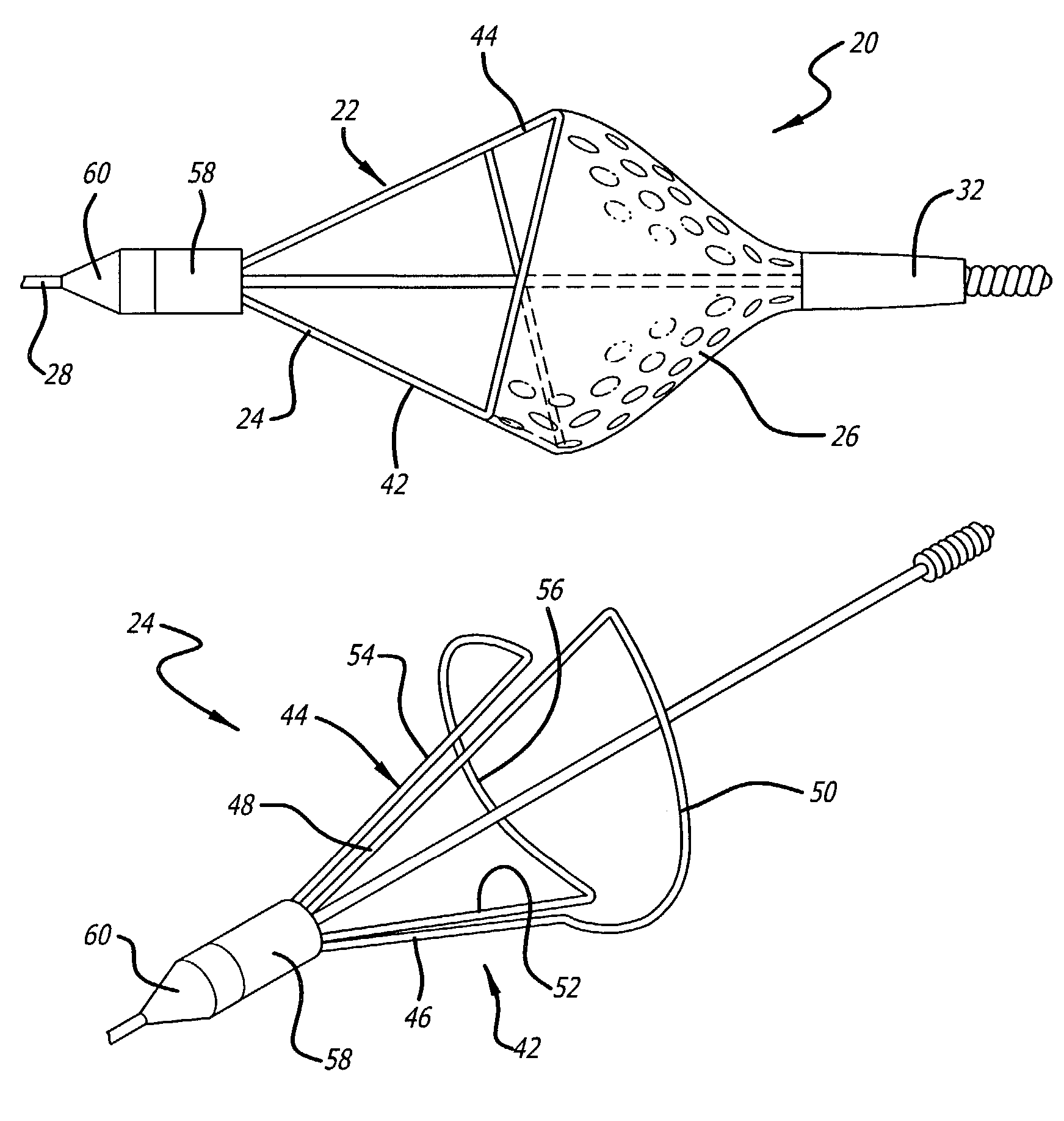
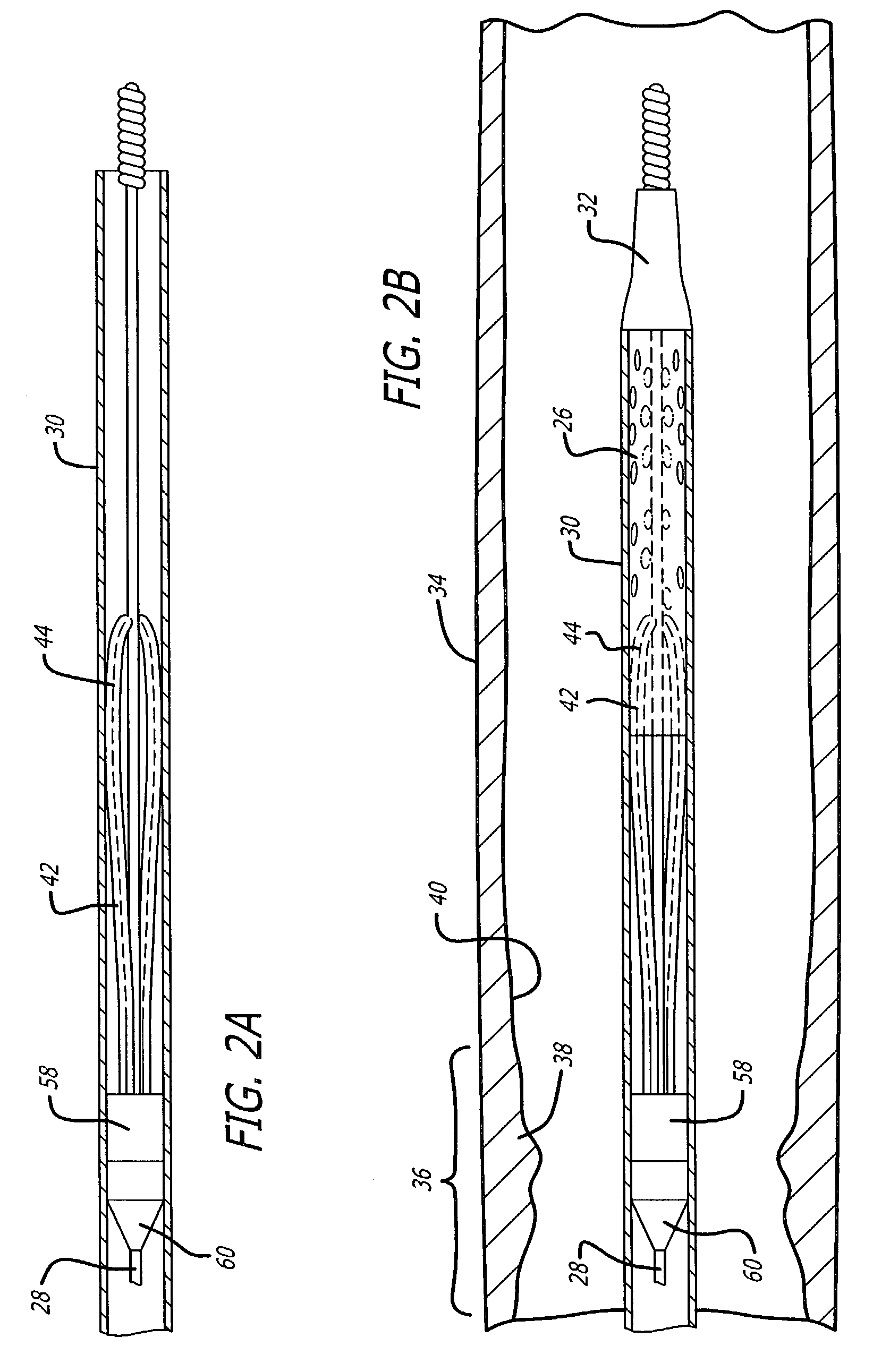
[0056]Turning now to the drawings, in which like reference numerals represent like or corresponding elements in the drawings, FIGS. 1A, 1B and 1C illustrate one particular embodiment of an embolic filtering device 20 incorporating features of the present invention. This embolic filtering device 20 is designed to capture embolic debris which may be created and released into a body vessel during an interventional procedure. The embolic filtering device 20 includes an expandable filter assembly 22 having a self-expanding frame 24 and a filter element 26 attached thereto. In this particular embodiment, the expandable filter assembly 22 is rotatably mounted on the distal end of an elongated tubular or solid shaft, such as a steerable guide wire 28. A restraining or delivery sheath 30 (see FIGS. 2A–2C) extends coaxially along the guide wire 28 in order to maintain the expandable filter assembly 22 in its unexpanded position until it is ready to be deployed within the patient's vasculature...


PUM


Abstract

An expandable frame for an embolic filtering device used to capture embolic debris in a body vessel includes a first half frame having a first control arm connected to a second control arm by a partial loop and a second half frame having a first control arm connected to a second control arm by a partial loop. The partial loops cooperatively form a composite loop for attachment of a filtering element which will expand in the body vessel to capture embolic debris entrained in the fluid of the vessel. The lengths and positioning of the first and second control arms of each half frame can be varied to create an expandable frame which conforms to the size and shape of the body vessel in which the filtering device is deployed. Additionally, the radius of the partial loops, along with the length of the arc of the partial loops, can be varied on each of the frames to create a composite filtering assembly that can easily adapt to the size and shape of the body vessel. Additionally, the control arms of the half frames can be disposed either proximally or distally of the composite loop to create a distinct filtering structure.

Description

FIELD OF THE INVENTION[0001]The present invention relates generally to filtering devices and systems which can be used when an interventional procedure is being performed in a stenosed or occluded region of a body vessel to capture embolic material that may be created and released into the vessel during the procedure. The present invention is more particularly directed to an embolic filtering device made with a self-expanding frame (also referred to as a basket or cage) having enhanced flexibility and bendability. The present invention is particularly useful when an interventional procedure, such as balloon angioplasty, stenting procedure, laser angioplasty or atherectomy, is being performed in a critical body vessel, such as the carotid arteries, where the release of embolic debris into the bloodstream can occlude the flow of oxygenated blood to the brain, resulting in grave consequences to the patient. While the present invention is particularly useful in carotid procedures, the i...

Claims


Application Information

Patent Timeline
Patent Type & Authority Patents(United States)
IPC IPC(8): A61M29/00A61F2/01
CPCA61F2/013A61F2002/015A61F2230/008A61F2002/018A61F2230/0006A61F2/0108
Inventor DENISON, ANDY E.HARRISON, WILLIAM J.HUTER, BENJAMIN C.HUTER, SCOTT J.PAPP, JOHN E.SAVILLE, STEVEN T.STALKER, KENT C. B.
Owner ABBOTT CARDIOVASCULAR
Learn More