Torque track system

a torque track and torque technology, applied in the direction of drilling machines and methods, rotary drilling, percussion drilling, etc., can solve the problems of time-consuming and/or difficult transportation of torque track systems, and difficulty in disassembling torque track systems in such a manner,

Active Publication Date: 2017-11-30
NABORS DRILLING TECH USA INC
View PDF3 Cites 0 Cited by
  • Summary
  • Abstract
  • Description
  • Claims
  • Application Information

AI Technical Summary

Benefits of technology

[0004]In accordance with one aspect of the present disclosure, a drilling rig includes a torque track system configured to couple to a derrick and to a top drive of the drilling rig, where the torque track system is configured to resist movement of the top drive in a lateral direction with respect to the derrick and to transfer torsional loads to the derrick in an operating configuration, a first torque track segment of the torque track system, and a second torque track segment of the torque track system coupled to the first torque track segment with a joint. The joint is configured to enable the first torque track segment and the second torque track segment to pivot with respect to one another while maintaining a physical connection between the first torque track segment and the second torque track segment during manipulation of the torque track system into and out of the operating configuration.
[0005]In accordance with another aspect of the present disclosure, a torque track system includes a plurality of torque track segments, where a first end torque track segment of the plurality of torque track segments couples the torque track system to a first end of a drilling rig, and where a second end torque track segment of the plurality of torque track segments couples the torque track system to a second end of the drilling rig, and a plurality of joints configured to couple the plurality of torque track segments to one another, where each joint of the plurality of joints include a connector and one or more knuckles secured to the connector by a fastener of a plurality of fasteners, and where the one or more knuckles are configured to rotate within grooves of the connector such that each torque track segment of the plurality of torque track segments pivots relative to one another from an operating configuration to a stacked configuration.

Problems solved by technology

Assembling and disassembling a torque track system may present various challenges.
Additionally, torque track systems may be bulky and / or difficult to transport to and from the well location.
As may be appreciated, assembling or disassembling a torque track system in such a manner may be time consuming and difficult to perform.

Method used


Image

  • Torque track system
  • Torque track system
  • Torque track system

Examples


Embodiment Construction

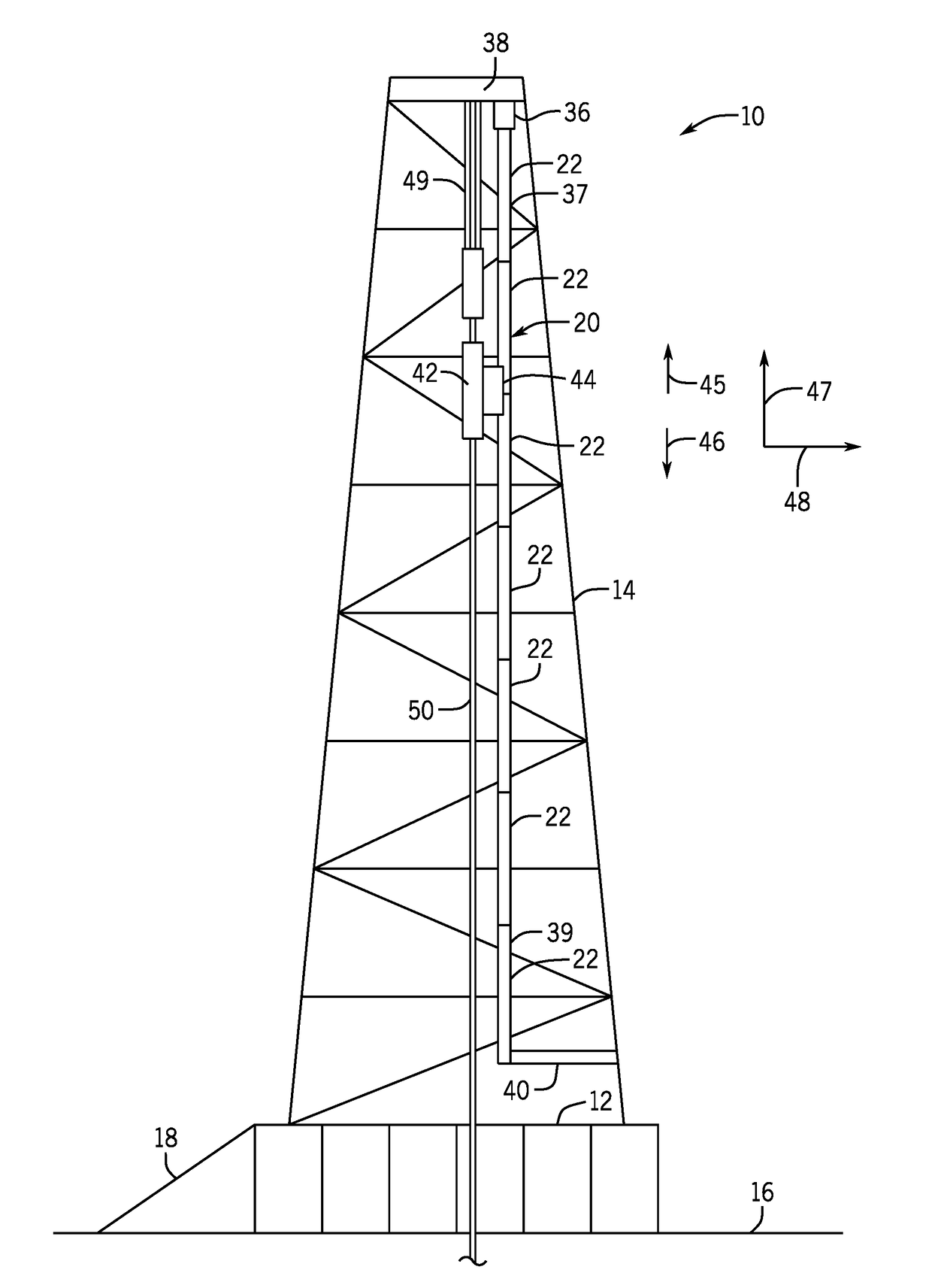
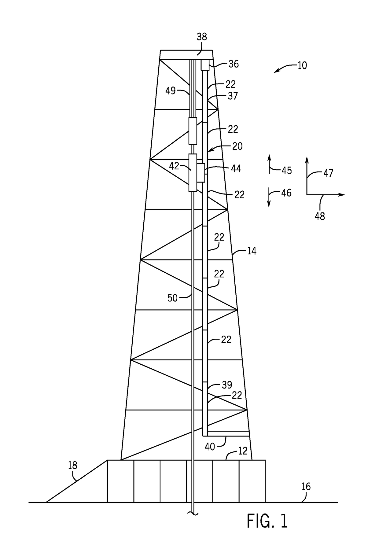
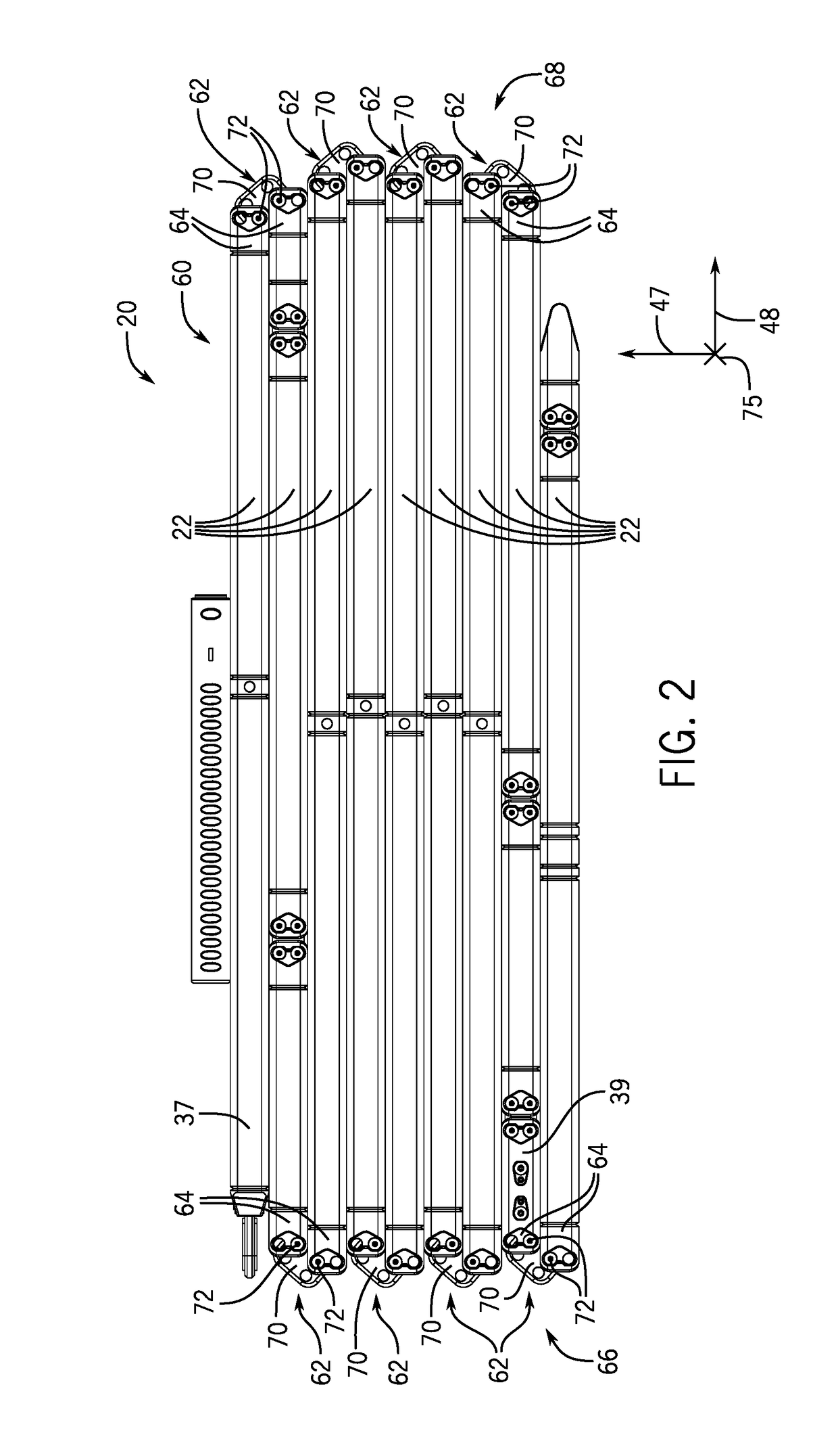
[0019]The present disclosure provides an improved top drive torque track system and methods for manipulating the top drive torque track system. As used herein, the term “manipulating” may refer to assembling, disassembling, or both. The presently disclosed techniques enable segments of a torque track system to fold (e.g., stack) on top of one another to facilitate manipulation of the torque track system and to reduce a compacted or disassembled size of the torque track system, thereby facilitating transportation of the torque track system. As such, in one embodiment, segments of the torque track system may be coupled to one another with a rotatable joint. The rotatable joint may include one or more fasteners that are configured to both lock adjacent segments in place and to enable rotation of two adjacent segments with respect to one another. Further, the fasteners may maintain a physical connection between torque track segments of the torque track system when the torque track syste...


PUM


Abstract

A drilling rig includes a torque track system configured to couple to a derrick and to a top drive of the drilling rig, where the torque track system is configured to resist movement of the top drive in a lateral direction with respect to the derrick and to transfer torsional loads to the derrick in an operating configuration, a first torque track segment of the torque track system, and a second torque track segment of the torque track system coupled to the first torque track segment with a joint. The joint is configured to enable the first torque track segment and the second torque track segment to pivot with respect to one another while maintaining a physical connection between the first torque track segment and the second torque track segment during manipulation of the torque track system into and out of the operating configuration.

Description

BACKGROUND[0001]The present disclosure relates generally to the field of drilling and processing of wells, and, more particularly, to a torque track system and method for assembling the torque track system.[0002]In conventional oil and gas operations, a well is typically drilled to a desired depth with a drill string, which may include drillpipe, drill collars, and a bottom hole drilling assembly. The drill string may be turned by a rotary table and kelly assembly or by a top drive. A top drive typically includes a quill, which is a short length of pipe that couples with the upper end of the drill string, and one or more motors configured to turn the quill. The top drive is typically suspended from a traveling block above the rig floor so that it may be raised and lowered throughout drilling operations.[0003]The top drive is attached to a torque track system that extends from a bottom portion to a top portion of the derrick. The torque track system guides the top drive as it moves b...

Claims


Application Information

Patent Timeline
Patent Type & Authority Applications(United States)
IPC IPC(8): E21B15/00E21B3/02
CPCE21B3/02E21B15/00E21B3/022
Inventor MASON, AARON EDWARDGREENING, DOUGLAS CHRISTIAN
Owner NABORS DRILLING TECH USA INC
Why Eureka
Try Eureka