Magnetization device for a nuclear magnetic flow meter

a magnetic flow meter and magnetic separator technology, applied in measurement devices, instruments, acoustic wave reradiation, etc., can solve the problems of inability to install under the sea, inability to allow real-time measurements, and high cost of test separators, so as to reduce production and time expenditure and achieve sufficient homogeneity of magnetic field

Active Publication Date: 2016-07-19
KRONE GMBH
View PDF16 Cites 0 Cited by
  • Summary
  • Abstract
  • Description
  • Claims
  • Application Information

AI Technical Summary

Benefits of technology

[0010]The primary object of the present invention is to devise a magnetization device with reduced production and time expenditure which will achieve sufficient homogeneity of the magnetic field that permeates the fluid.
[0013]In one preferred embodiment of the magnetization device in accordance with the invention, the friction in the movement of the permanent magnets in the hollow profiles is reduced by lining of the hollow profiles, for example, with a polytetrafluoroethylene (PTFE) coating on the inner surfaces of the hollow profiles. The reduced friction distinctly reduces the expenditure of force for introducing the permanent magnets into the hollow profiles. After introducing the permanent magnets into the hollow profiles, the permanent magnets can be fixed in the hollow profiles by a first liquid adhesive and then a hardening substance. Sealing compounds, for example, are possible for this purpose.
[0015]As the holder of the receiving tubes, the carrier can have at least one disk with receivers for the receiving tubes in which there is, preferably, a penetration for the measurement tube. Usually the receiving tubes of a magnetization device are of the same length so that the holder of the receiving tubes can be a disk on each end of the receiving tubes. The carrier then is comprised essentially of the receiving tubes and the two disks. If there is to be a homogenous magnetic field in the measurement tube along the longitudinal axis of the measurement tube, the alignment of the longitudinal axes of the receiving tube parallel to the longitudinal axis of the measurement tube is possible. Often, the permanent magnets are located in the receiving tubes as a Halbach array.
[0018]In another preferred embodiment of the magnetization device in accordance with the invention, at least one of the hollow profiles in at least one of the profile bodies of the carrier is made such that there is an adapter tube in this hollow profile that is able to rotate and the adapter tube can be fixed against rotation. In each of the adapter tubes, a hollow profile for accommodating at least one of the permanent magnets is made. The rotation of the adapter tube is a first shimming to improve the homogeneity of the magnetic field in the measurement tube.
[0019]In another quite especially preferred embodiment of the magnetization device of the invention in accordance with the invention, the carrier comprises at least two profile bodies and two profile bodies at a time are detachably connected by at least one positively shaped connecting profile on the first profile body and at least one negatively shaped connecting profile on the second profile body. The positive and the negative connecting profile are shaped such that two connected profile bodies can execute translational movement against one another only along one axis. By this type of connection, the profile bodies can be easily arranged, for example, around the measurement tube, and thus, the magnetization device can be easily installed.

Problems solved by technology

Test separators are expensive, cannot be installed under the sea and do not allow real-time measurements.
In particular, test separators are, however, unable to reliably measure crude oil proportions smaller than 5%.
Since the crude oil proportion of each source drops continuously and the crude oil proportion of a plurality of sources is already less than 5%, it is currently impossible to exploit these sources.
Heterogeneities in the magnetic field therefore reduce the measurement quality of nuclear magnetic flow meters, for which reason the task of the magnetization device is the permeation of the fluid with a magnetic field which is ordinarily homogeneous within the measurement tube.
Due to the plurality of bar magnets which are arranged tightly in each of the magnet disks, the introduction of the bar magnets into the magnet receivers is associated with a high expenditure of force.
Moreover, the resulting magnetic field is initially not homogenous enough, for which reason the magnetic field must be made homogeneous by manipulation on each of the bar magnets.
The introduction and shimming of the numerous bar magnets mean a considerable production and time expenditure, which is accompanied by the corresponding costs.

Method used


Image

  • Magnetization device for a nuclear magnetic flow meter
  • Magnetization device for a nuclear magnetic flow meter
  • Magnetization device for a nuclear magnetic flow meter

Examples


Embodiment Construction

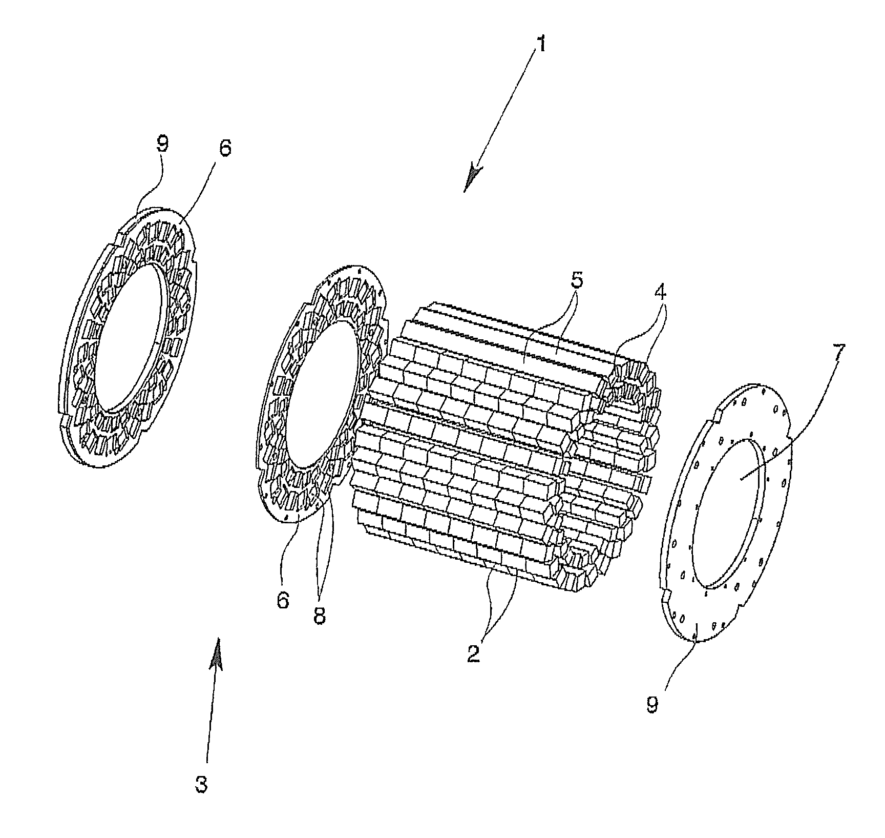
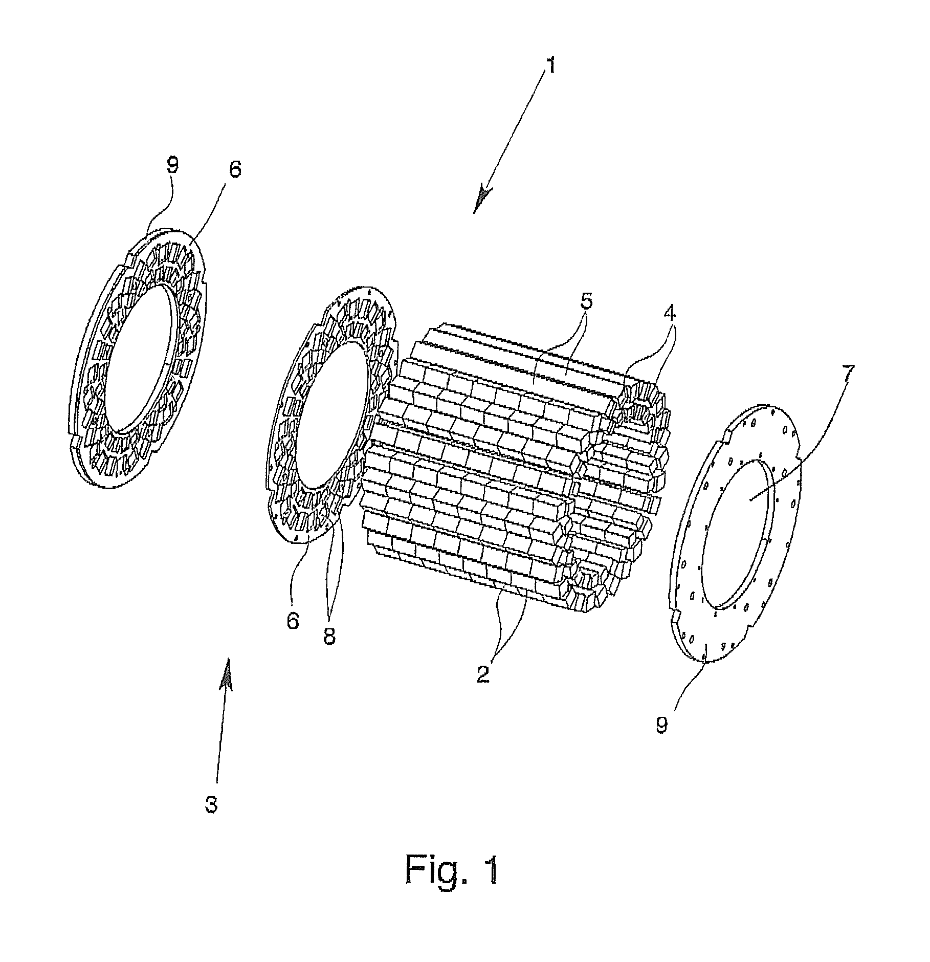
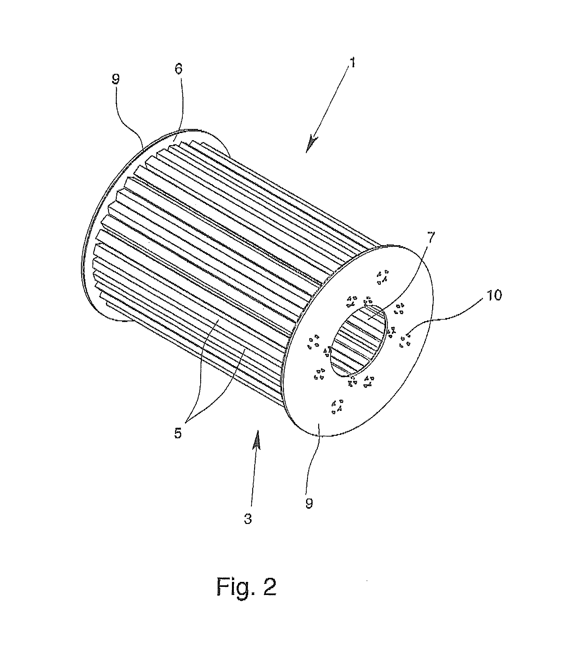
[0026]FIG. 1 shows the essential components of a magnetization device 1 in accordance with the invention; there are a plurality of permanent magnets 2 and a carrier 3 made of nonmagnetic material. The primary components of the carrier 3 are a plurality of receiving tubes 5 in the form of hollow profiles 4, two disk rings 6 with a central opening 7 for a measurement tube and with receivers 8 for the receiving tubes 5 and two end disk rings 9 which also have a central opening 7 for the measurement tube. In FIG. 1, not all receiving tubes 5 are visible in order to be able to show the permanent magnets 2 as well.

[0027]In each of the receiving tubes 5, eight permanent magnets 2 of the same length are introduced, the cross-sectional contour of these permanent magnets 2 being rectangular and form-fit with the hollow profiles 4 so that the permanent magnets 2 can be moved in one of the hollow profiles 4 only along the longitudinal axis of the hollow profile 4, but cannot turn around the lon...


PUM


Abstract

A magnetization device for permeation of a multiphase fluid flowing through a measurement tube of a nuclear magnetic flow meter with a magnetic field which is homogenous at least in one plane, with a plurality of permanent magnets for generation of a magnetic field and with a carrier, the carrier having at least one magnet receiver, each magnet receiver accommodating at least one of the permanent magnets, the shape of the magnet receivers and of the permanent magnets allowing movement of the permanent magnets in the magnet receivers only in one direction and the permanent magnets being by the magnet receivers formed by hollow profiles. The hollow profile magnet receivers can be receiving tubes for the magnets that can be turned around their longitudinal axis or the profiles can have a rotatable adapter for the magnets so that a first shimming action can be achieved with the profiles.

Description

BACKGROUND OF THE INVENTION[0001]1. Field of the Invention[0002]The invention relates to a magnetization device for permeation of a multiphase fluid flowing through a measurement tube of a nuclear magnetic flow meter with a magnetic field which is homogenous at least in one plane, with a plurality of permanent magnets for generation of a magnetic field and with a carrier, the carrier having at least one magnet receiver, each of the magnet receivers accommodating at least one of the permanent magnets, the shape of the magnet receivers and of the permanent magnets allowing movement of the permanent magnets only in one direction in the magnet receivers and the permanent magnets held by the magnet receivers being arranged by the magnet receivers with reference to the magnetic field.[0003]2. Description of Related Art[0004]A nuclear magnetic flow meter determines the flow of the individual phases of a multiphase fluid, the flow velocities of the individual phases and the relative proport...

Claims


Application Information

Patent Timeline
Patent Type & Authority Patents(United States)
IPC IPC(8): G01V3/00G01F1/716G01F1/74
CPCG01F1/716G01F1/74
Inventor PORS, JAN TEUNIS AARTHOGENDOORN, CORNELIUS JOHANNESDE GRAAF, ARIELZOETEWEIJ, MARCO LEENDERT
Owner KRONE GMBH
Why Eureka
Try Eureka