
Wiring and connection management system for installation of LED light engines

Active Publication Date: 2016-08-02
ELEMENTAL LED
View PDF23 Cites 29 Cited by
  • Summary
  • Abstract
  • Description
  • Claims
  • Application Information

AI Technical Summary

Benefits of technology

The patent text describes a system where power distribution members, like printed circuit boards, are used to provide flexibility in installing LED light engines and other elements requiring power. The system also includes surface-mount connectors that make it easy to install LED light engines with little training. The use of rigid power distribution members, like PCBs, makes the system more robust and easier to install. The technical effect of this system is that it provides more flexibility and ease of installation for LED light engines and other elements requiring power.

Problems solved by technology

LEDs require relatively little power, operate at low temperatures, have long life spans, are mechanically robust, and have a small footprint, especially when compared with traditional incandescent, and even fluorescent, light bulbs.
However, configuring LEDs to function in different applications often presents engineering challenges of its own.
One major engineering challenge in configuring LEDs for particular applications is the wiring and cabling necessary to supply the LEDs with power.
In situations where there are several strips or sets of LEDs (e.g., when each shelf of a shelving unit is to be individually lit), the resulting plethora of cords and cables can become an unwieldy tangle, and necessary solder joints can break, if the installers do not take special care to arrange and organize them when the LEDs are installed.
However, even a careful, correct LED installation can leave numerous cables dangling—and with all of those cables, it can be difficult to determine whether or not the installation is correct, and equally difficult to prevent accidental damage or disconnection in the field.

Method used


Image

  • Wiring and connection management system for installation of LED light engines
  • Wiring and connection management system for installation of LED light engines
  • Wiring and connection management system for installation of LED light engines

Examples


Embodiment Construction

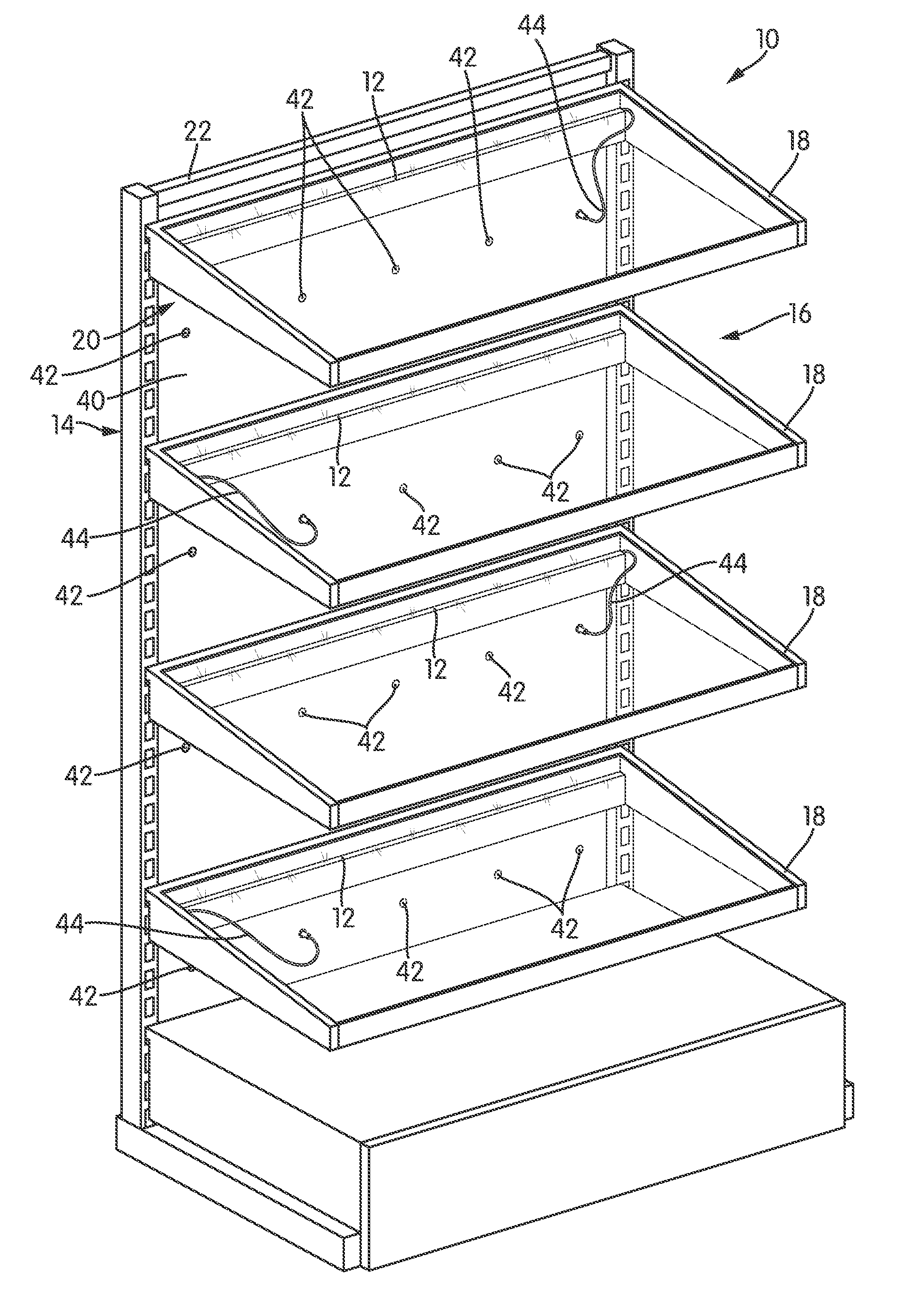
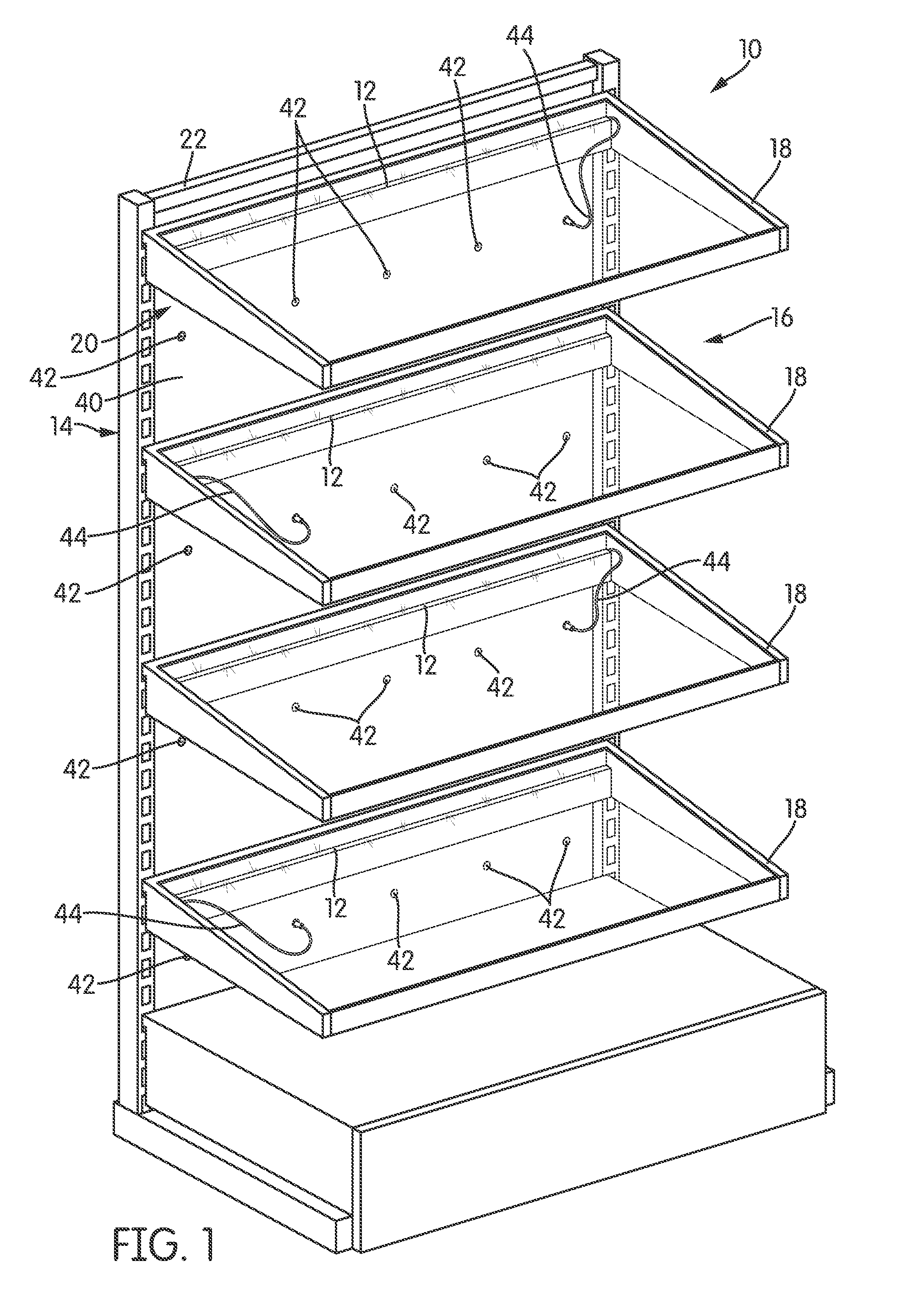
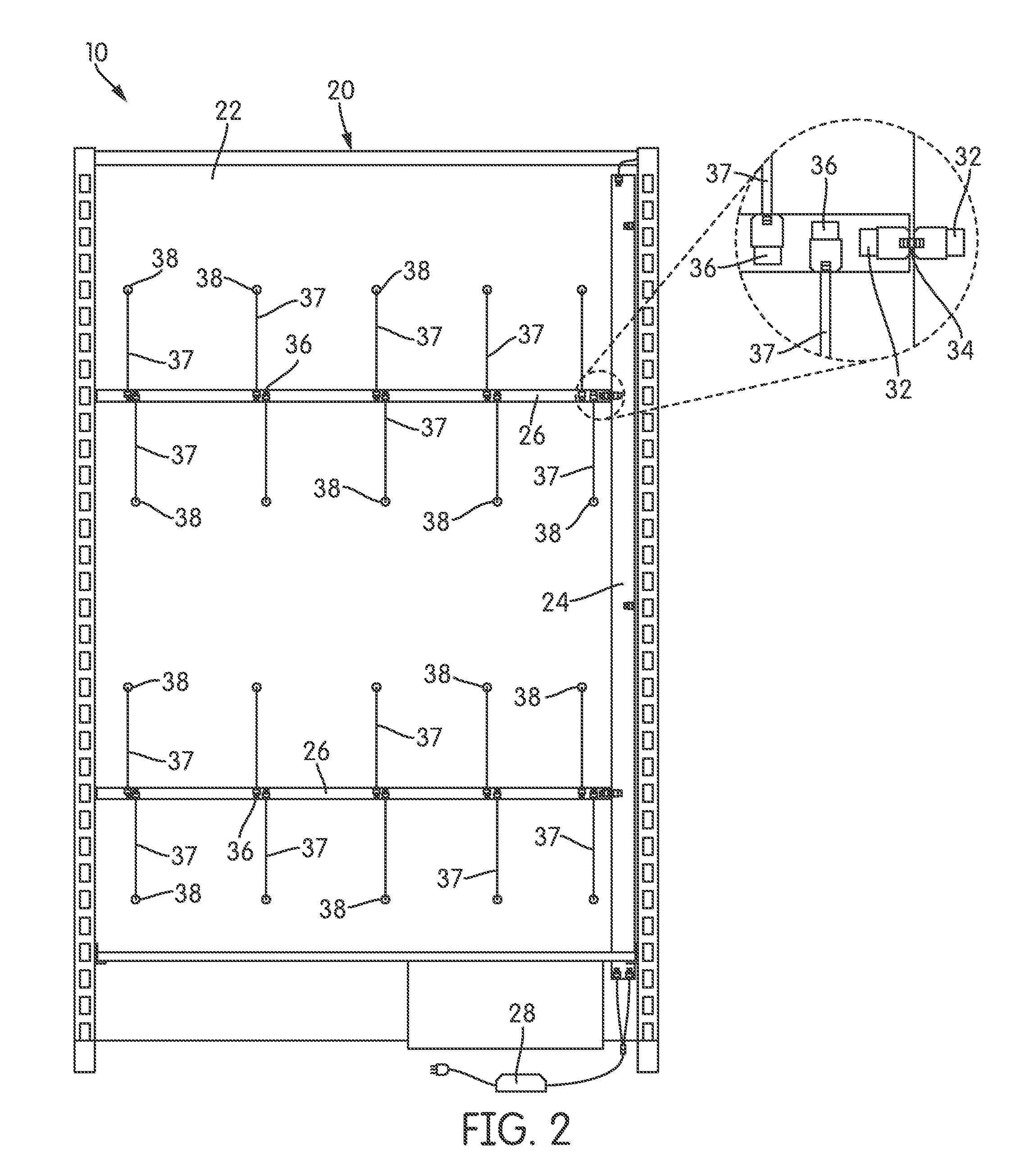
[0019]FIG. 1 is a perspective view of a wiring and cable management system, generally indicated at 10, which supplies power to a number of LED light engines 12. The LED light engines 12 of this embodiment are rigid PCBs with LEDs installed, and are arranged to illuminate individual shelves of a shelving unit 14. In the illustrated embodiment, the shelving unit 14 is a gondola shelving unit with a plurality of shelves 18.

[0020]The wiring and cable management system 10 has broad use in a variety of applications. While FIG. 1 illustrates its use in a gondola shelving unit 14, the wiring and cable management system 10 is particularly advantageous in any type of installation where the wiring for the LED light engines 12 is to be hidden. The substrate on which the system 10 is installed may be a shelving unit of another type; a piece of furniture, such as a desk, cabinet or armoire; a door; or a wall or wall panel, to name but a few options. Typically, the substrate (in this case, the she...


PUM


Abstract

A wiring and connection management system is disclosed. The system comprises a set of power distribution members that are attached to a substrate and are connected together, forming a power grid to distribute power across the substrate. The members include a number of connectors disposed at regular intervals along their lengths. Corresponding sets of cables and connectors on the substrate convey power from the members to areas on the substrate where power is desired. The substrate may be, for example, a shelving unit. The system provides a robust, flexible source of power that is easily installed with minimal training and is also easily maintained.

Description

BACKGROUND OF THE INVENTION[0001]1. Field of the Invention[0002]The invention relates to wiring and connection management systems for installation of light-emitting diodes (LEDs).[0003]2. Description of Related Art[0004]In the last 15 years, light-emitting diodes (LEDs) have gone from an extravagant curiosity in the lighting industry to a viable and vital lighting source in any number of applications. LEDs require relatively little power, operate at low temperatures, have long life spans, are mechanically robust, and have a small footprint, especially when compared with traditional incandescent, and even fluorescent, light bulbs. All of those attributes make LEDs very advantageous to use in a variety of applications in which traditional lighting technologies would require too much space or generate too much heat, or when accessing and replacing traditional light bulbs would be too laborious or difficult. Additionally, the plethora of LED products on the market offer a variety of lig...

Claims


Application Information

Patent Timeline
IPC IPC(8): H01R4/60F21V23/00F21V23/06F21V23/02H02B1/015H02B1/20H01R25/14A47F5/10F21V21/34
CPCF21V23/001F21V23/02F21V33/0012F21V23/06F21S2/00F21W2131/301F21Y2115/10H01R25/14F21V21/34A47F5/103A47F3/001A47F11/10F21Y2103/10A47B57/36A47B96/02H05K1/0215H05K1/111
Inventor FENG, ROBERTPETERSEN, RUSSELL
Owner ELEMENTAL LED
Learn More