
Display device, in particular a head-mounted display, based on temporal and spatial multiplexing of hologram tiles

a display device and temporal and spatial multiplexing technology, applied in the field of display devices, can solve the problems of not meeting the demands of size and weight of devices such as this kind, and the 3d scene cannot be reconstructed in a small volume of view, and achieve the effect of high resolution

Active Publication Date: 2016-08-02
SEEREAL TECHNOLOGIES
View PDF14 Cites 38 Cited by
  • Summary
  • Abstract
  • Description
  • Claims
  • Application Information

AI Technical Summary

Benefits of technology

The technical effect of this patent is to modify an HMD device with a small number of modulator cells in the matrix to produce a high-resolution holographic reconstruction.

Problems solved by technology

In contrast to an HMD, devices of this kind do not make such great demands on size and weight.
In such an HMD, a 3D scene can only be reconstructed in a small volume of view.

Method used


Image

  • Display device, in particular a head-mounted display, based on temporal and spatial multiplexing of hologram tiles
  • Display device, in particular a head-mounted display, based on temporal and spatial multiplexing of hologram tiles
  • Display device, in particular a head-mounted display, based on temporal and spatial multiplexing of hologram tiles

Examples


Embodiment Construction

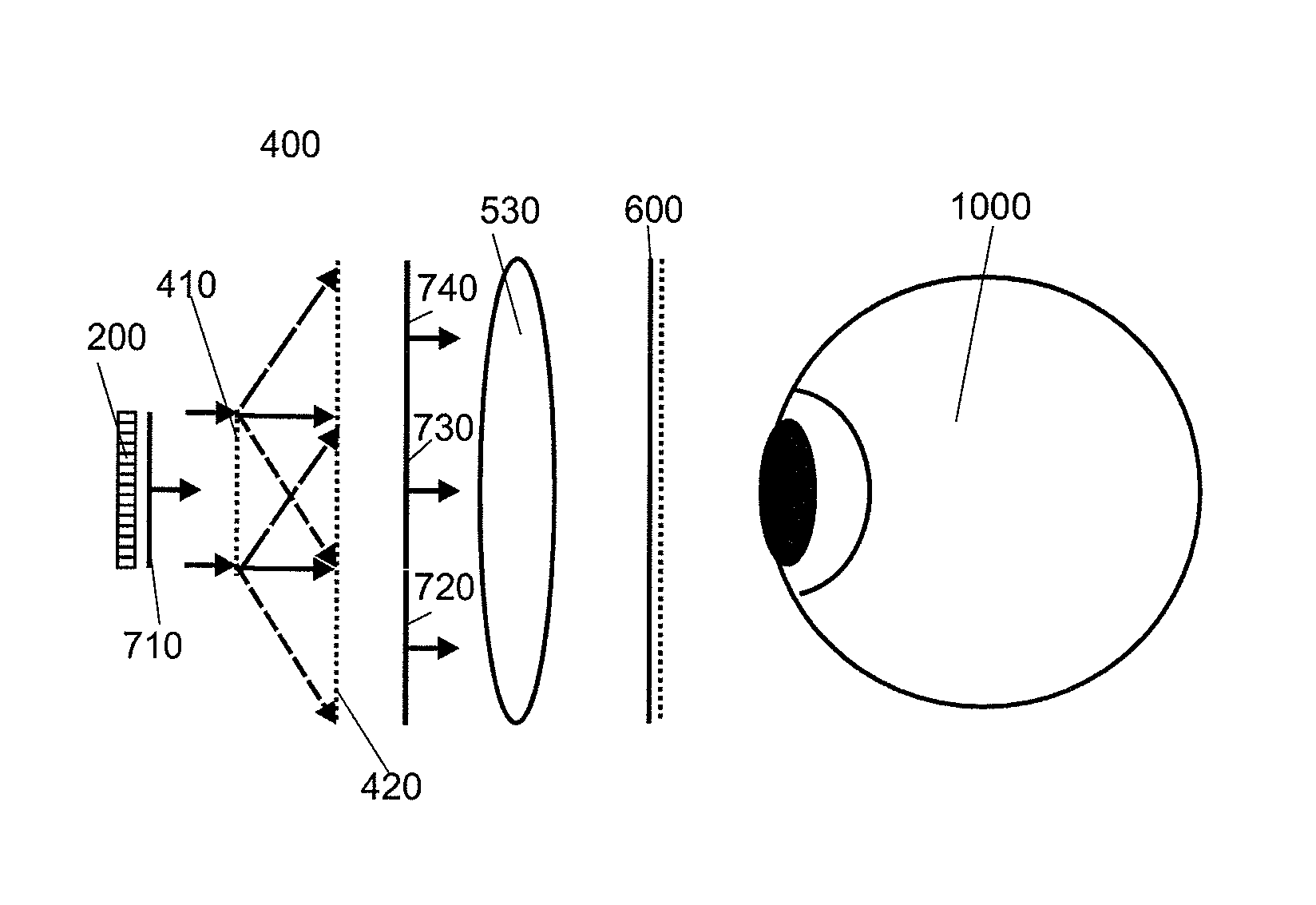
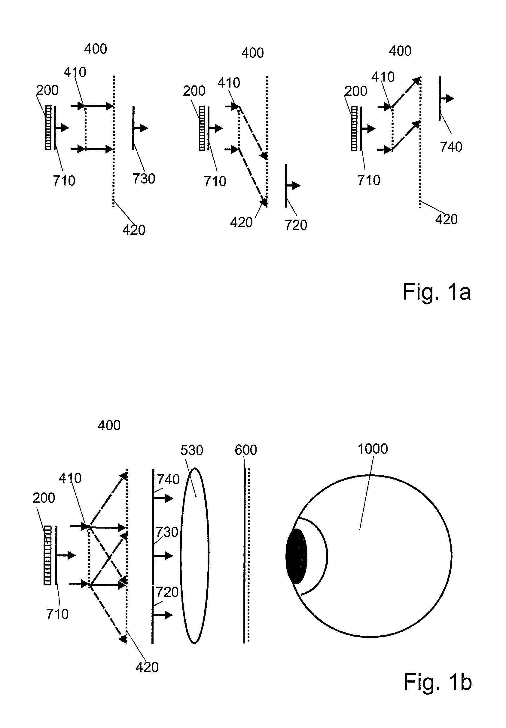
[0167]FIGS. 1a and 1b each show a light-deflecting device 400 with several general functions as shall be used in the HMD device according to this invention.

[0168]Referring to FIG. 1a, the light-deflecting device 400 comprises two controllable light-deflecting means 410, 420 which image a spatial light modulator SLM 200 multiple times with multiple coherent wave fronts 720, 730, 740. The SLM 200 is illuminated with collimated light by an illumination device (not shown). After the modulation of the light by the SLM 200 a modulated coherent wave front 710 is emitted by the SLM.

[0169]In a modified preferred embodiment, the SLM 200 is illuminated with a converging wave front. An optional beam combiner (not shown) is then adapted to that type of illumination.

[0170]If the beam combiner is based, for example, on a birefringent coplanar plate (Savart plate), as proposed by the applicant in document DE 10 2009 044910 A1, the thickness of this plate shall be modified depending on the position ...


PUM


Abstract

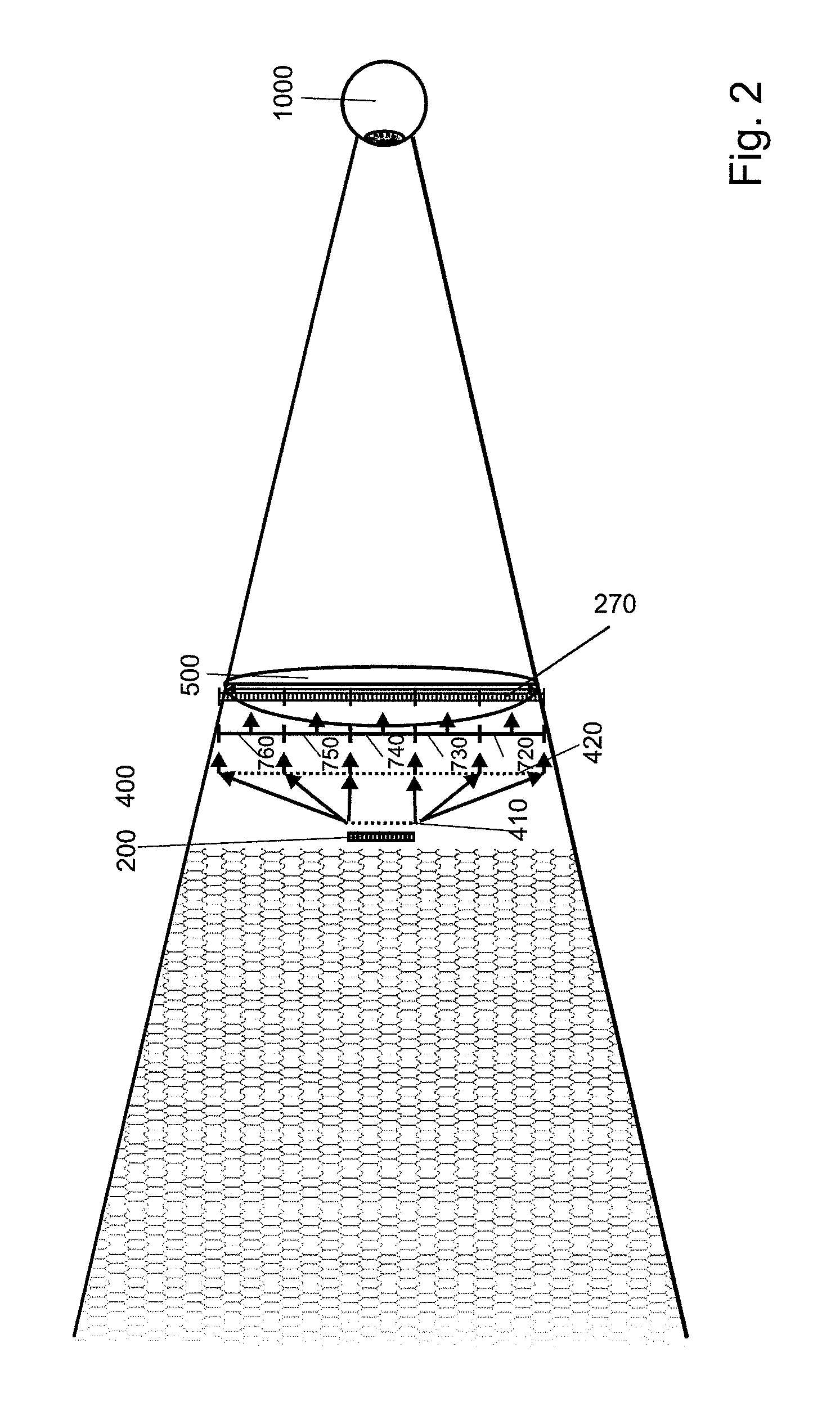
The invention relates to a display device, in particular a head-mounted display or hocular, having a spatial light modulator and a controllable light-deflecting device for generating a multiple image of the spatial light modulator, which consists of segments, the multiple image being produced at least with a predefinable number of segments which determines the size of a visible area within which a 3D-scene holographically encoded in the spatial light modulator can be reconstructed for observation by an eye of an observer.

Description

CROSS REFERENCE TO RELATED APPLICATIONS[0001]This application claims the priority of PCT / EP2011 / 069485, filed on Nov. 4, 2011, which claims priority to German Application No. 10 2010 043 557.0, filed Nov. 8, 2010; German Application No. 10 2011 078 027.0, filed Jun. 23, 2011, and German Application No. 10 2011 053 710.4, filed Sep. 16, 2011, the entire contents of all of which are hereby incorporated in total by reference.BACKGROUND OF THE INVENTION[0002]The present invention relates to a display device which generates a holographic reconstruction in a relatively large reconstruction space (volume of view) with the help of a multiple compound image of a spatial light modulator (SLM).[0003]Generally, visual display devices serve for users to watch, for example, two-dimensional video information, computer-generated stereo images or holographically generated information of a three-dimensional scene.[0004]In addition to display devices where a generated image or a reconstructed 3D scene...

Claims


Application Information

Patent Timeline
IPC IPC(8): G02B27/14G02B27/01G02B27/22G02B5/32G06T15/50G03H1/26H04N13/04G02F1/29G03H1/22G03H1/04
CPCG02B5/32G02B27/0172G02B27/2214G03H1/2294G03H1/26H04N13/044G06T15/50G02F1/29G03H1/2205G03H2001/0491G03H2001/2236G03H2001/2284G03H2001/2292G03H2001/2297G03H2001/2655G03H2223/19G03H2223/21G03H2225/11G03H2225/25G03H2225/33G03H2225/60G03H2226/05G03H2225/55H04N13/344G02F1/292G02B30/27G02B6/0016G02B26/12G02B27/0037G02B27/0103G02B27/0179G02B27/58G02B2027/0134G02B2027/0187G03H1/268
Inventor FUTTERER, GERALD
Owner SEEREAL TECHNOLOGIES
Learn More