
Asymmetric MAMR head with self-aligned spin torque oscillator along flare edge for shingled magnetic recording

a technology of asymmetric mamr head and flare edge, which is applied in the direction of manufacturing head surface, data recording, instruments, etc., can solve the problems of inability to obtain the desired magnetic field gradient, insufficient strength, and inability to increase the magnetic field gradient at the track edg

Active Publication Date: 2016-08-02
WESTERN DIGITAL TECH INC
View PDF19 Cites 22 Cited by
  • Summary
  • Abstract
  • Description
  • Claims
  • Application Information

AI Technical Summary

Problems solved by technology

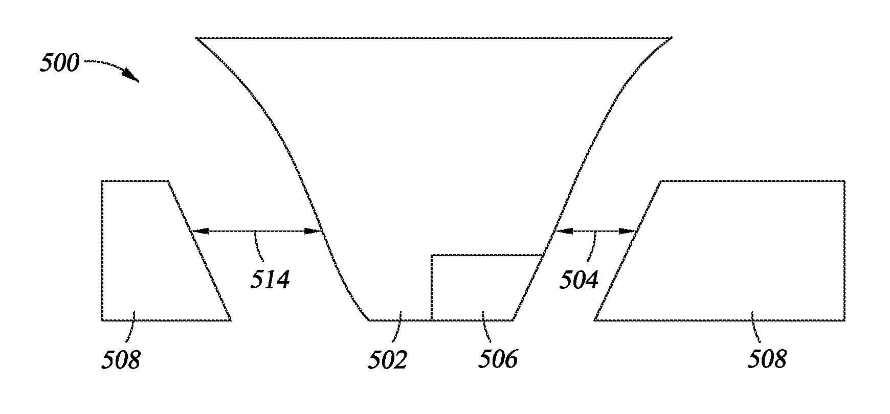
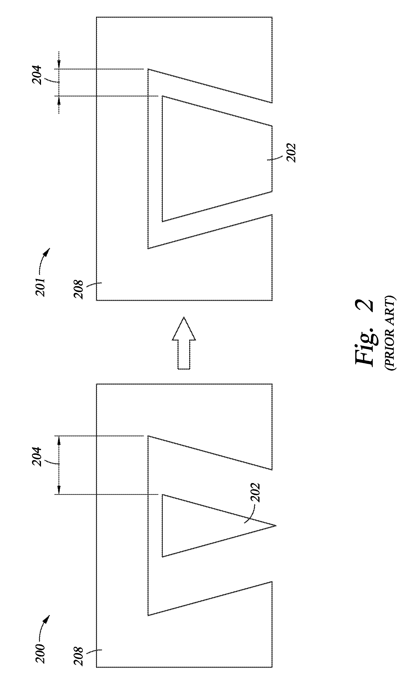
However, by only narrowing the side gaps 204 in magnetic head 201, the problem of the absorption of the magnetic field into the side shields 208 and inadequate strength arose, and consequently, the inability to obtain the desired magnetic field gradient.
By only placing the STO in the center of the main pole on the trailing shield side of the main pole, the magnetic field gradient at the track edge could not be increased, and adequate gain could not be obtained by the MAMR-SMR technique.
This results in the degradation of the cross track gradient of the write magnetic field.

Method used


Image

  • Asymmetric MAMR head with self-aligned spin torque oscillator along flare edge for shingled magnetic recording
  • Asymmetric MAMR head with self-aligned spin torque oscillator along flare edge for shingled magnetic recording
  • Asymmetric MAMR head with self-aligned spin torque oscillator along flare edge for shingled magnetic recording

Examples


Embodiment Construction

[0028]In the following, reference is made to exemplified embodiments. However, it should be understood that the invention is not limited to specific described embodiments. Instead, any combination of the following features and elements, whether related to different embodiments or not, is contemplated to implement and practice the invention. Furthermore, although embodiments of the invention may achieve advantages over other possible solutions and / or over the prior art, whether or not a particular advantage is achieved by a given embodiment is not limiting of the invention. Thus, the following aspects, features, embodiments and advantages are merely illustrative and are not considered elements or limitations of the appended claims except where explicitly recited in a claim(s). Likewise, reference to “the invention” shall not be construed as a generalization of any inventive subject matter disclosed herein and shall not be considered to be an element or limitation of the appended clai...


PUM

PropertyMeasurementUnit
angleaaaaaaaaaa
thicknessaaaaaaaaaa
heightaaaaaaaaaa

Abstract

The present disclosure generally relates to the structure of a perpendicular magnetic write head for use in a magnetic disk drive. A shingled-microwave-assisted magnetic recording head for use in a high-areal-density hard disk drive comprises a trailing shield, a flare-shaped main pole, one or more side shields, a spin torque oscillator, and two asymmetric side gaps, where one side gap has a smaller width than the other side gap. The spin torque oscillator shares a first continuous edge with the main pole on a side adjacent the side gap having the smaller width and shares a second continuous edge adjacent a media facing surface. The angle of the spin torque oscillator and the main pole formed by the media facing surface and the narrow side gap is greater than about 90°.

Description

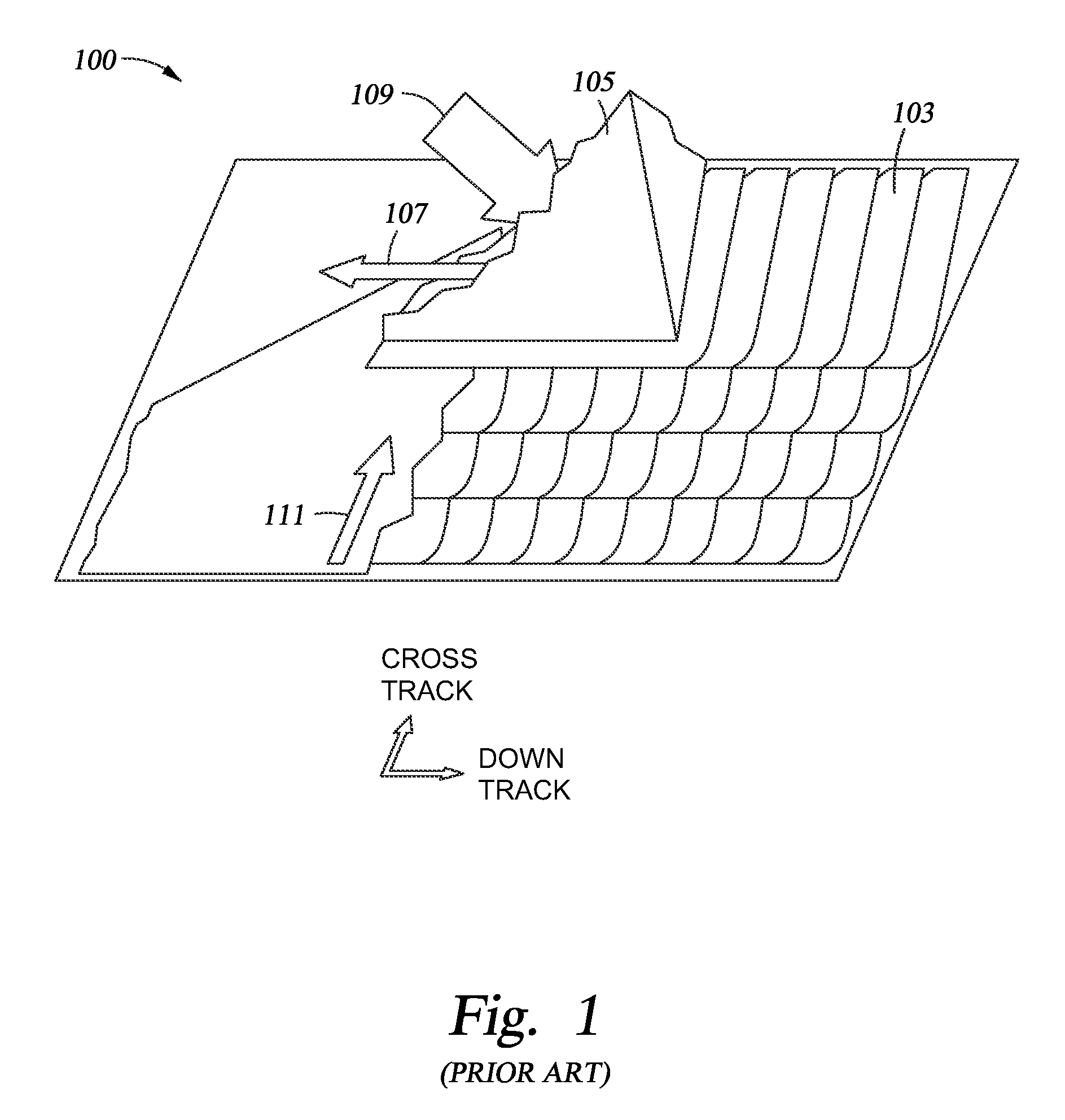
BACKGROUND OF THE INVENTION[0001]1. Field of the Invention[0002]Embodiments disclosed herein generally relate to the structure of a perpendicular magnetic write head for use in a magnetic disk drive.[0003]2. Description of the Related Art[0004]Over the past few years, shingled magnetic recording (SMR) has been studied as a recording technique for improving the areal density. FIG. 1 shows a diagram 100 of one example of the SMR technique. In this technique, multiple tracks 103 overlap and are written in a shingle pattern. A partial view of a magnetic recording head 105 is shown and the magnetic recording head 105 moves over the tracks 103 in the direction of the arrow 107, while progressive scans are in the direction of the arrow 111. Magnetic flux is applied to the magnetic recording head 105 in the direction of the arrow 109. With the SMR technique, an actual read track is written by using the end of the main pole, and thus, the write characteristics in the end of the main pole are...

Claims


Application Information

Patent Timeline
Patent Type & Authority Patents(United States)
IPC IPC(8): G11B5/31G11B5/23G11B5/127G11B5/00
CPCG11B5/315G11B5/3133G11B5/1278G11B5/23G11B5/3113G11B5/3143G11B2005/0024
Inventor URAKAMI, YOSUKESHIIMOTO, MASATOKUDO, KAZUESHIINA, HIROMI
Owner WESTERN DIGITAL TECH INC
Learn More