
Capturing device, capturing method, and capturing program

a technology of capturing device and capturing program, which is applied in the direction of line-of-sight transmission, satellite communication transmission, electrical apparatus, etc., can solve the problems of large beam displacement, limited communication distance up to about 100 km, and difficult to maintain long-distance optical communication

Active Publication Date: 2016-08-02
NEC CORP
View PDF20 Cites 7 Cited by
  • Summary
  • Abstract
  • Description
  • Claims
  • Application Information

AI Technical Summary

Benefits of technology

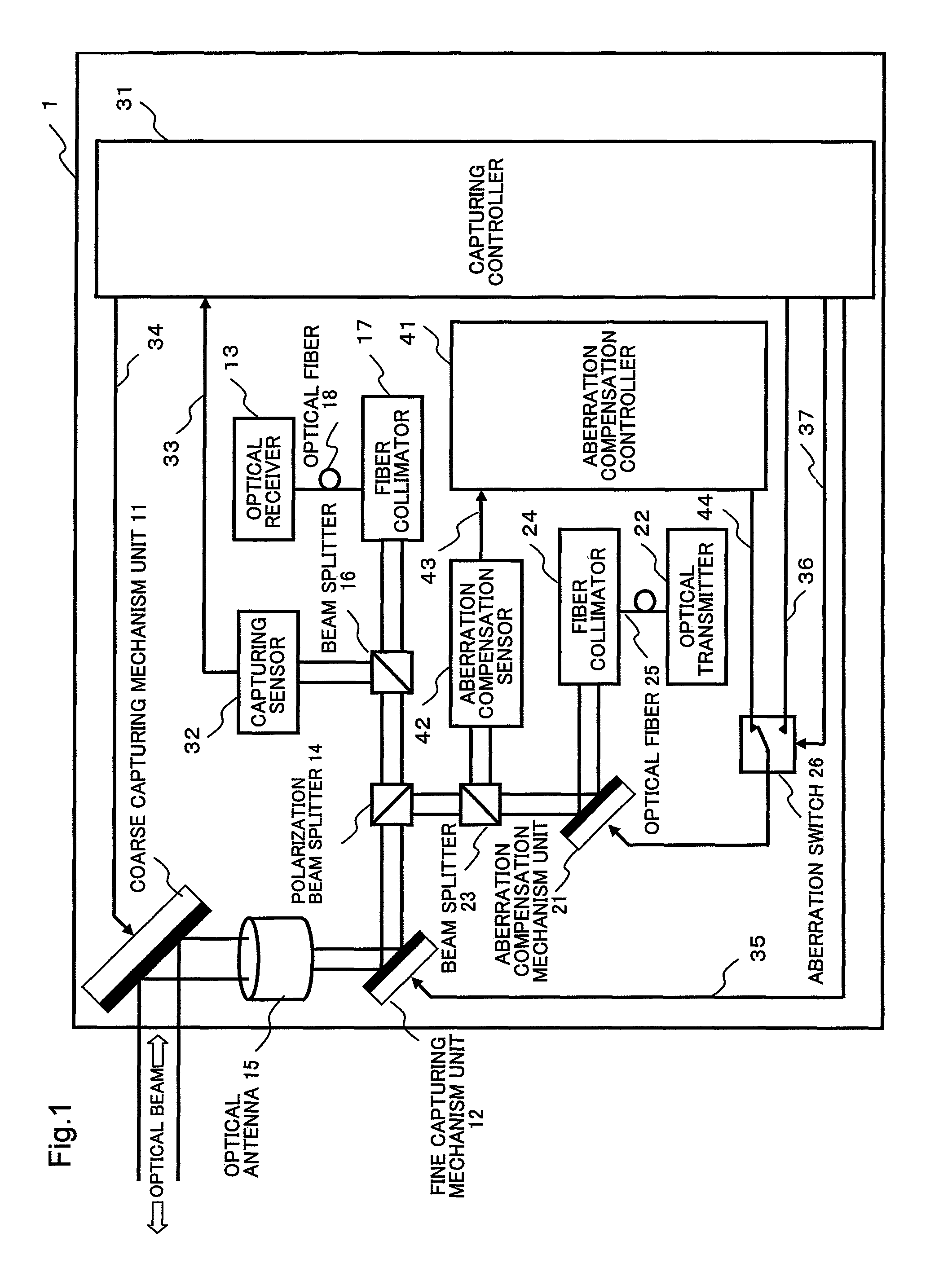
[0041]A capturing device, a capture method and a capturing program of the present invention can obtain an effect on completing capturing operation in a short time period without using beacon light based on carrying out scanning operation and capturing operation simultaneously.

Problems solved by technology

However, in the fiber optics communication, due to loss in optical fibers and wavelength dispersion or the like, the communication distance is limited up to about 100 km.
Further, in the optical communication, because the communication distance is long, large displacement of beam at a communication destination occurs caused by a slight fluctuation in position and angle of communication devices due to a vibration or the like.
Therefore, it is difficult to maintain a long-distance optical communication while fixing the direction of the beam even it is between artificial satellites each other in geostationary orbit of the earth.
It is difficult to realize such requirements by one mechanism.
However, because a diffusion angle of beam used for usual communication is narrow, it is difficult to predict a direction of the communication partner with accuracy as much a diffusion angle of beam.
However, in such a capturing device, because it needs to scan the whole scanning range more than once using a narrow scanning beam, it needs a long time for the scanning operation.
As a result, the capturing time at the partner's device also becomes long.

Method used


Image

  • Capturing device, capturing method, and capturing program
  • Capturing device, capturing method, and capturing program
  • Capturing device, capturing method, and capturing program

Examples


second exemplary embodiment

[0195]According to the first exemplary embodiment, although it has been described that the coarse capturing mechanism unit 11 was a configuration which changes the direction of the reception beam and the transmission beam directly, the coarse capturing mechanism unit may also be a configuration as a table device which is equipped with the fine capturing mechanism unit.

[0196]FIG. 6 is a block diagram showing the entire structure of a capturing system 2 according to the second exemplary embodiment of the present invention. The capturing system 2 of this exemplary embodiment is constituted by including a control device 3 which controls the whole, a capturing device 4 which performs the fine capturing operation and the scanning operation and a coarse capturing mechanism unit 19 which is controlled by the control device 3 and performs the coarse capturing operation.

[0197]The control device 3 performs the same control as each controller of the first exemplary embodiment.

[0198]The coarse c...

third exemplary embodiment

[0206]The first exemplary embodiment has described the scanning operation using the aberration compensation mechanism unit 21. However, it is enough for the scanning operation that it can scan the transmission beam, and the scanning operation can be realized by using other configurations.

[0207]Further, as the scanning path of the transmission beam, the first exemplary embodiment has described the path having a spiral shape from a center or an outer circumference. However, the capturing device 1 can use different paths as the scanning paths as it has been already described.

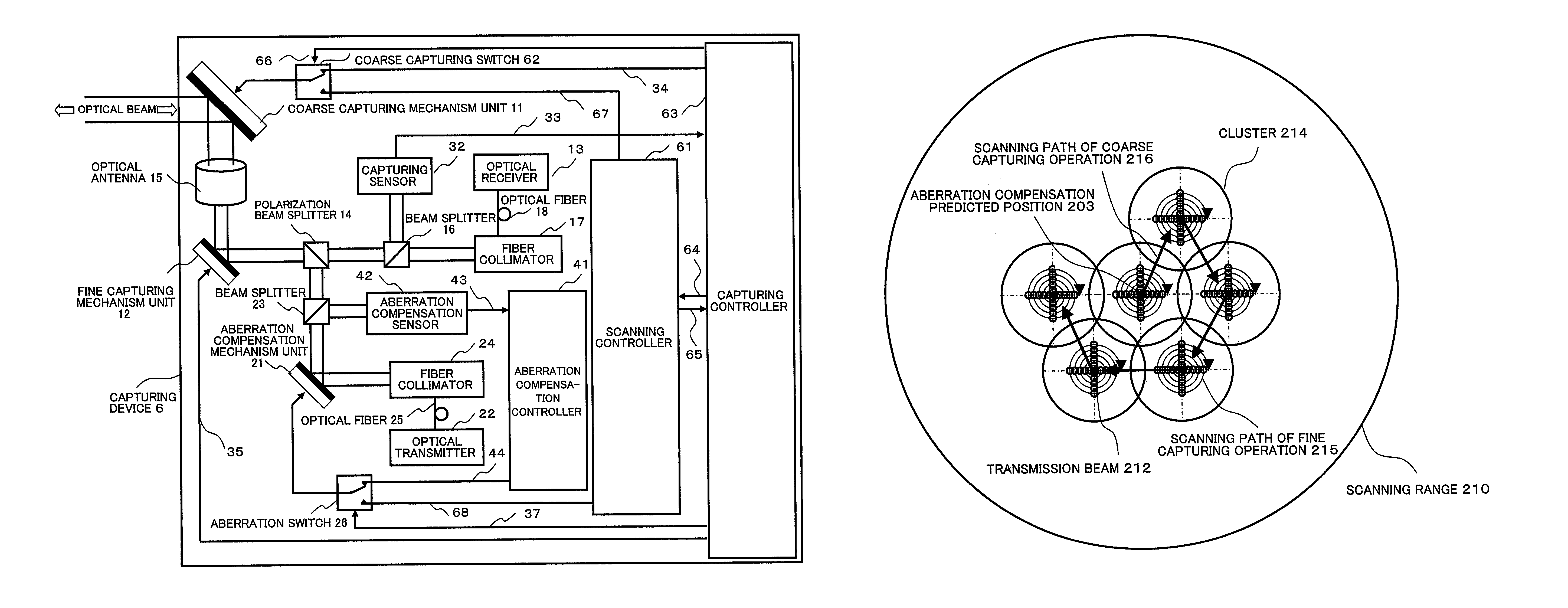
[0208]FIG. 11 is a block diagram showing a configuration of a capturing device 6 according to the third exemplary embodiment of the present invention.

[0209]The capturing device 6 according to the third exemplary embodiment performs the scanning operation using the coarse capturing mechanism unit 11 in addition to the aberration compensation mechanism unit 21. Therefore, the capturing device 6 includes a scanning co...


PUM


Abstract

There have been problems that a capturing device requires an optical source having a large power output, and a scanning operation and a capturing operation must be alternately performed by the respective devices.A capturing device is provided with an optical receiver which receives a beam from outside as a reception beam, a reception beam capturing unit which performs a capturing operation by which the reception beam is introduced to the optical receiver, an optical transmitter which generates a transmission beam transmitted to the outside, a transmission beam scanning unit which performs a scanning operation of the transmission beams, and an optical circulator wherein the incidence of the reception beam and the exit of the transmission beam are performed at the same terminal.

Description

CROSS REFERENCE TO RELATED APPLICATIONS[0001]This application is a National Stage of International Application No. PCT / JP2010 / 060929 filed on Jun. 21, 2010, which claims priority from Japanese Patent Application Nos. 2009-167627, filed on Jul. 16, 2009 and 2009-289435 filed Dec. 21, 2009, the contents of all of which are incorporated herein by reference in their entirety.TECHNICAL FIELD[0002]The present invention relates to a capturing device, a capturing method and a capturing program and in particular, relates to a capturing device, a capturing method and a capturing program of a communication beam in an optical communication.BACKGROUND ART[0003]As a communication using light, a fiber optics communication using optical fibers is known. The fiber optics communication uses a low-loss optical fiber and a semiconductor laser, and is developing as a long distance communication network. However, in the fiber optics communication, due to loss in optical fibers and wavelength dispersion o...

Claims


Application Information

Patent Timeline
Patent Type & Authority Patents(United States)
IPC IPC(8): H04B10/00H04B10/112H04B10/118
CPCH04B10/1121H04B10/118H04B10/1123
Inventor AOKI, KAZUHIKO
Owner NEC CORP
Learn More