Microfluidic card connection device

a technology of microfluidic cards and connection devices, which is applied in the direction of laboratory apparatus, instruments, material analysis, etc., can solve the problems of easy inability to connect cards to instruments, and easy inability to achieve the effect of ensuring the connection

Active Publication Date: 2016-08-09
COMMISSARIAT A LENERGIE ATOMIQUE ET AUX ENERGIES ALTERNATIVES
View PDF32 Cites 1 Cited by
  • Summary
  • Abstract
  • Description
  • Claims
  • Application Information

AI Technical Summary

Benefits of technology

[0020]When the openings of the channels formed in the card and the device, which are intended to be connected, include seals, such a rotary motion enables a shearing stress on the seals to be prevented when the card is pressed against the second surface of the device.
[0025]A combination of such forces allows the card to be pressed against the device in optimum fashion.
[0027]A means of ensuring watertightness or airtightness, for example a seal, may be positioned at the opening of such a channel in order to allow a watertight or airtight fluid connection with a channel of the card, when the latter is held against the device. A seal may also be positioned in the opening of a channel of the card. A rotary motion around an axis, as explained above, enables all friction or sliding in the seals to be prevented.
[0036]The closest ends of the first surface and of the second surface are preferably separated by a distance equal to or greater than 1.1 times or 1.2 times the thickness of a card which may be connected to the device. This enables the card to be introduced easily into the insertion area.

Problems solved by technology

The problem of connecting the card to an instrumented support is very often overlooked.
As a consequence, the techniques generally used are delicate and burdensome to implement, as is shown by the examples below.
And these moving means may go astray when they are used and, in addition, they require delicate handling when positioning and / or using them.
These handling operations may rapidly become burdensome when they are undertaken frequently.
Producing such a card is constrictive and costly.
In both cases, the steps of production, connection and disconnection of a microfluidic card to an instrumented support are lengthy and delicate.

Method used


Image

  • Microfluidic card connection device
  • Microfluidic card connection device
  • Microfluidic card connection device

Examples


Embodiment Construction

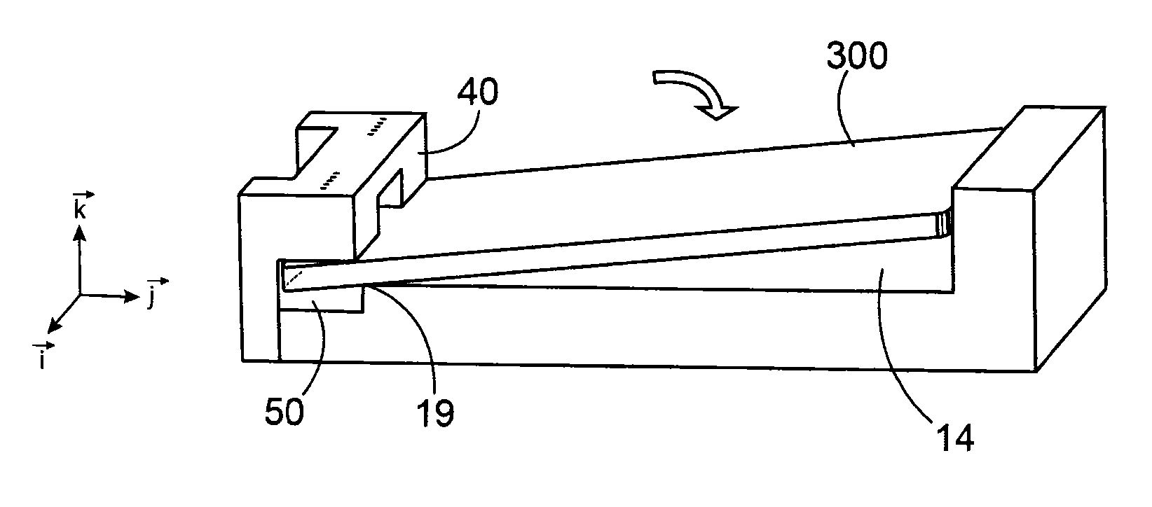
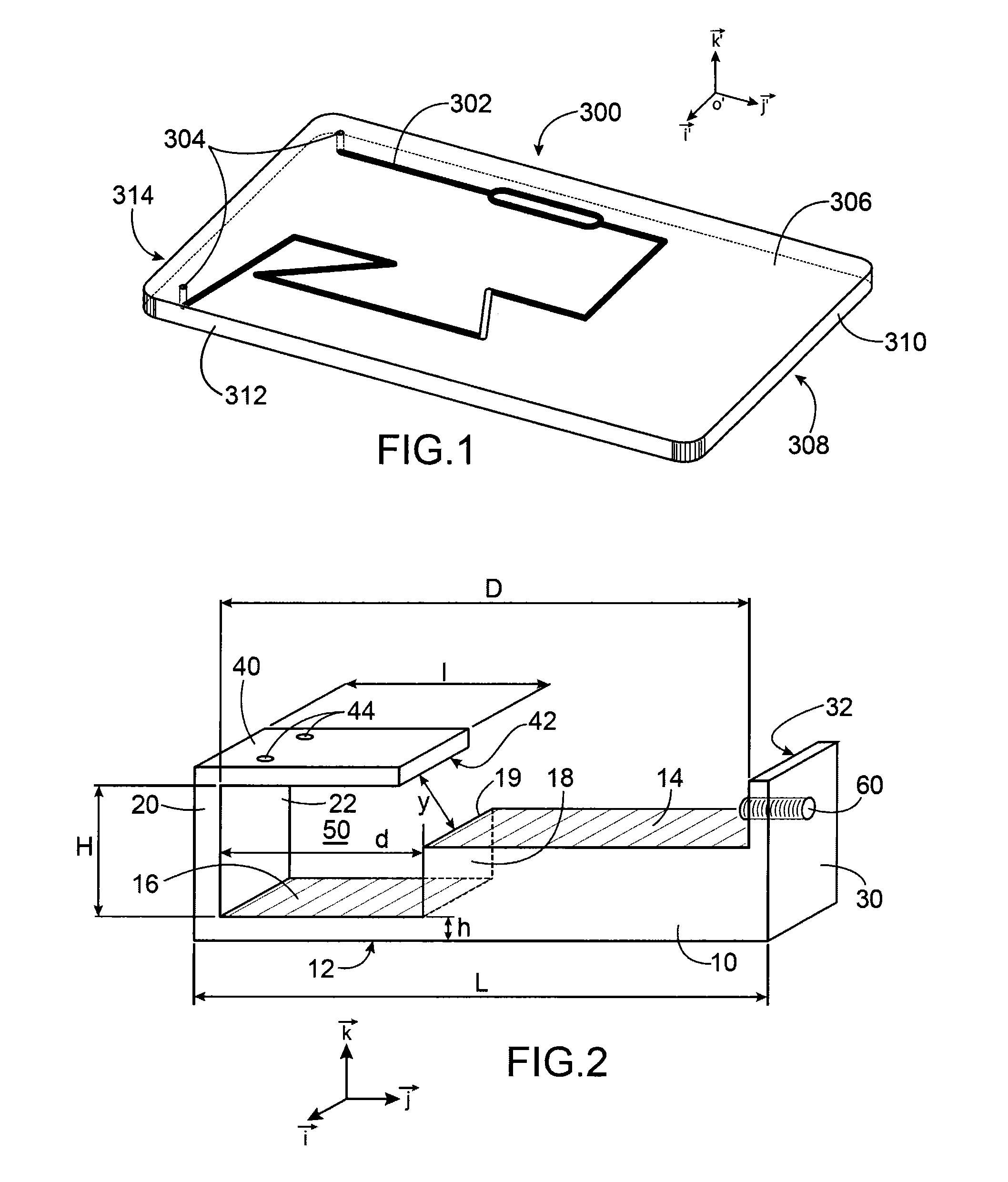
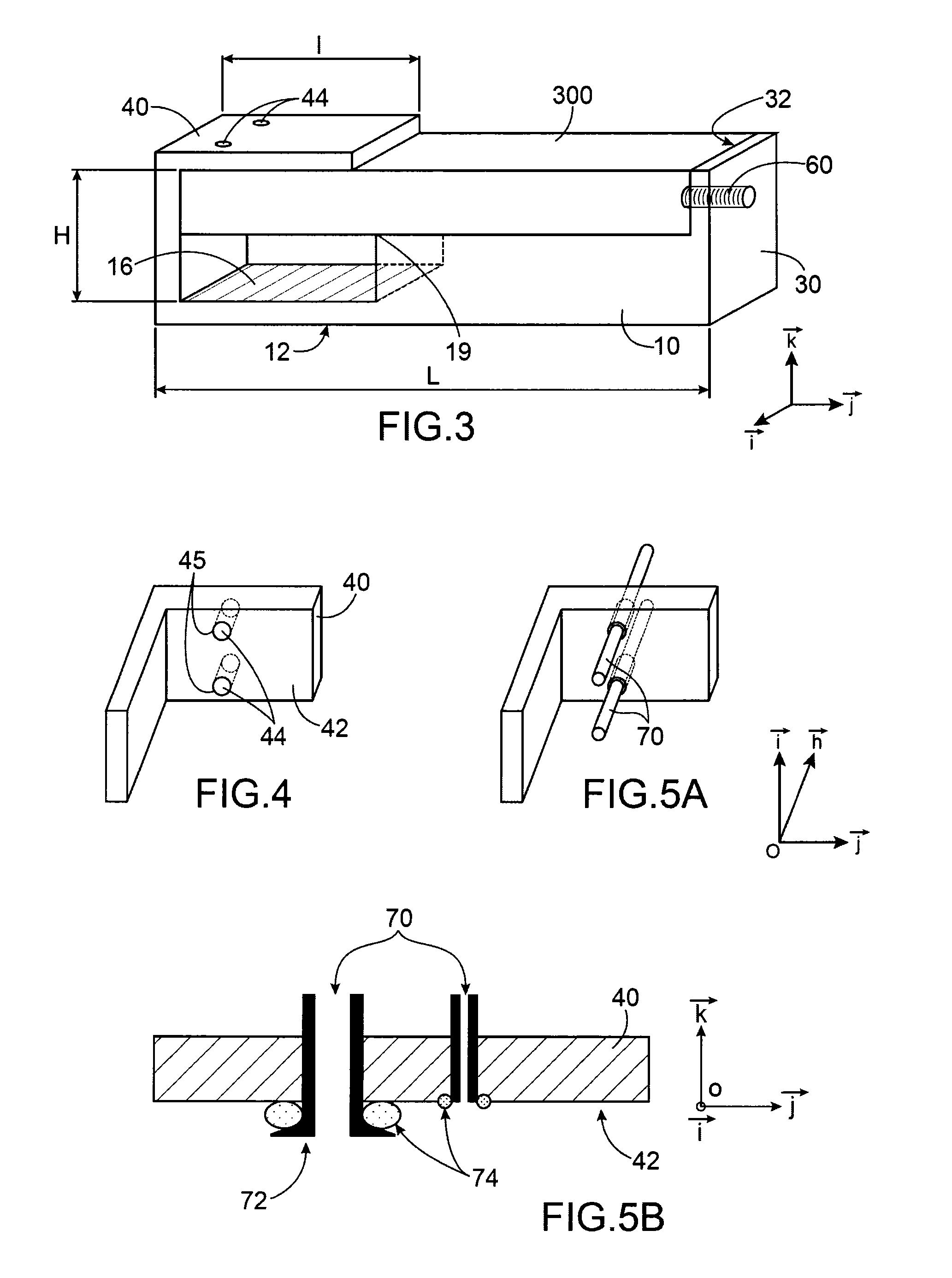
[0010]The invention relates to a device for interconnecting a card, where the card includes at least one first fluid channel, emerging from a connection side, where this side is parallel to a support side, and where the said interconnection device includes:[0011]a first surface, intended to receive the card's support side,[0012]a second surface parallel to the first surface, from which a second fluid channel emerges,[0013]means to hold the card in place, intended to hold the card's connection side pressed against the second surface of the device, such that the first fluid channel is in fluid connection with the second fluid channel.

[0014]A means defining an axis of rotation is defined, such that a card is able to tip or pivot around this axis and then be pressed against the first surface.

[0015]An interconnection device according to the invention enables a card to be connected to, or disconnected from, the said device.

[0016]The holding means are able to hold the card's support side a...


PUM

PropertyMeasurementUnit
thicknessaaaaaaaaaa
thicknessaaaaaaaaaa
thicknessaaaaaaaaaa

Abstract

A device for interconnecting a card including at least one first fluid channel, emerging from a connection side parallel to a support side, the interconnection device including: a first surface configured to receive the support side of the card; a second surface parallel to the first surface, from which a second fluid channel emerges; and a mechanism to hold the card in place, configured to hold a connection side of the card pressed against the second surface of the device, such that first fluid channel is in fluid connection with the second fluid channel.

Description

TECHNICAL FIELD[0001]The invention relates to a device for watertight or airtight connection and disconnection of a microfluidic card, with one or more instruments, such as for example a measuring device, a heating element, a mechanical actuator, a pump, etc.[0002]The invention relates to fields including those of medical research, biology and pharmaceuticals.[0003]The invention also relates to a method for connecting and disconnecting a microfluidic card in the said connection device, without tools and without particular technical knowledge.STATE OF THE PRIOR ART[0004]The use of in vitro diagnostic devices generally requires that a card, including a fluid circuit, is connected to an instrumented support. The term “card” is understood to mean a support made from a rigid material, which may include a fluid circuit. The card may, for example, include complex means, such as a biochip, a valve, a reaction chamber, etc. The problem of connecting the card to an instrumented support is ver...

Claims


Application Information

Patent Timeline
Patent Type & Authority Patents(United States)
IPC IPC(8): B01L3/00B01L9/00G01N21/01
CPCB01L3/502715B01L9/527B01L2200/025B01L2200/027B01L2200/028B01L2200/04B01L2200/0689Y10T29/49002B01L9/52B01J2219/00813B01L2300/0816B01J2219/0081
Inventor CHARLES, RAYMONDPOUTEAU, PATRICK
Owner COMMISSARIAT A LENERGIE ATOMIQUE ET AUX ENERGIES ALTERNATIVES
Why Eureka
Try Eureka