Valve train for internal combustion engine

A technology of valve mechanism and internal combustion engine, which is applied in the direction of machines/engines, mechanical equipment, engine components, etc. It can solve the problems of inaccurate flushness between the concave part and the conversion pin, so as to avoid clamping and deformation, avoid shear stress, and short response the effect of time

Inactive Publication Date: 2013-08-21
MAN ENERGY SOLUTIONS SA
View PDF0 Cites 0 Cited by
  • Summary
  • Abstract
  • Description
  • Claims
  • Application Information

AI Technical Summary

Problems solved by technology

The disadvantage of this solution is that the adjustment force of the switching part acting in the axial direction of the lever axis tries to force the first and second rocker apart in the axial direction, especially if the recess does not correspond to the switching pin. when exactly level with each other
Thus, disadvantageously, precise alignment of the shift pin and the recess accommodating it is required

Method used


Image

  • Valve train for internal combustion engine
  • Valve train for internal combustion engine
  • Valve train for internal combustion engine

Examples


Embodiment Construction

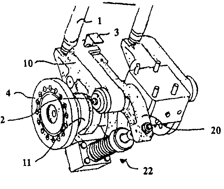
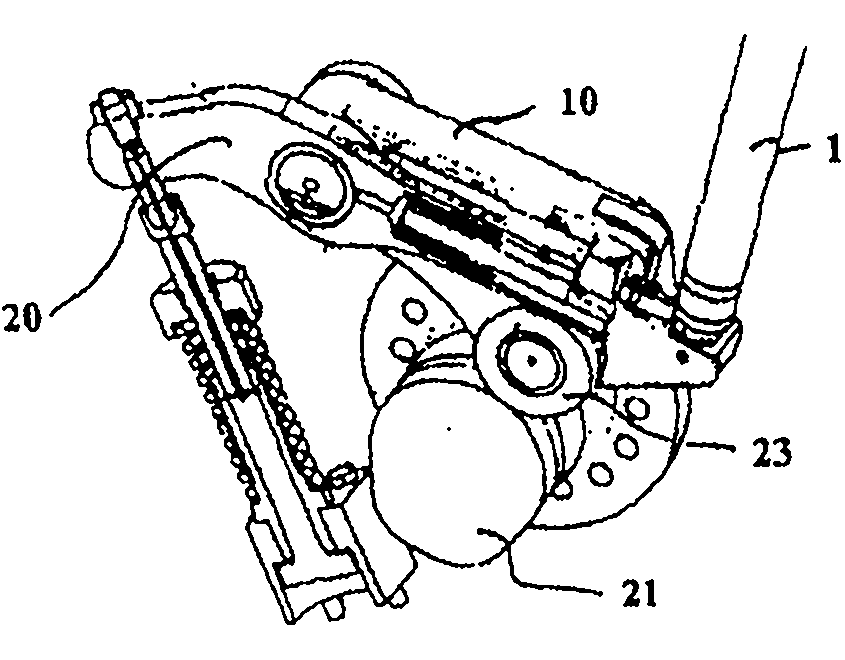
[0053] figure 1 A valve train according to an embodiment of the invention is shown in a perspective view. It comprises a main rocker 10 for actuating a valve lifter 1 and a switching rocker 20 adjacent thereto. The main rocker and switching rocker are mounted rotatably about the lever axis 2, wherein the main rocker 10 is counter to the direction of rotation D by the valve springs acting on the valve lifters 1 in a manner not shown in detail ( Figure 4 ) is preloaded. In the same way, the switching rocker 20 is prestressed against the direction of rotation D by means of a second return element 22 comprising a compression spring, so that both rockers 10 , 20 are prestressed against the camshaft 4 .

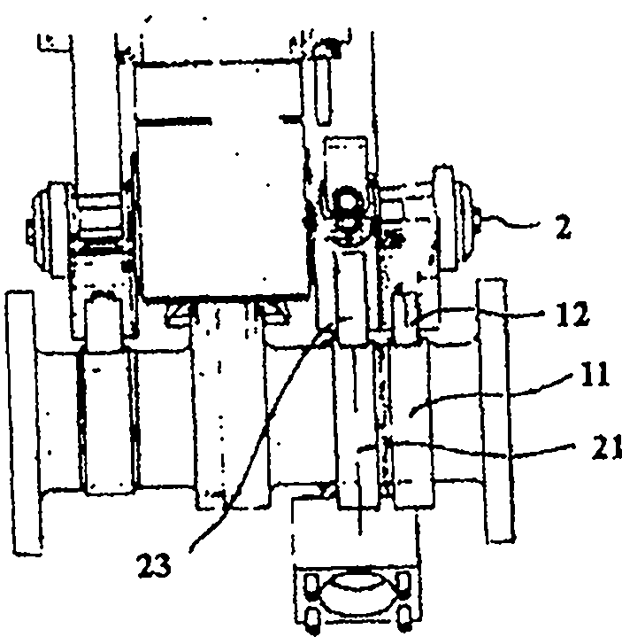
[0054] Here, the main rocker 10 utilizes rollers 12 ( image 3 ) is pressed against the first cam 11 of the camshaft 4 on which the roller 12 rolls, while the switching rocker 20 is pressed against the second cam 21 of such a camshaft 4 with the roller 23 in a corresponding man...


PUM


Abstract

PURPOSE: A valve train for an internal combustion engine is provided to prevent the displacement force of the switching element from acting in the axial direction of the valve lifter shaft, thereby reducing abnormal twist and deformation of the valve lifter. CONSTITUTION: A valve train for an internal combustion engine comprises a main valve lifter which rotates around a valve lifter shaft(2) in a rotational direction(D) by a first cam of a cam shaft, and a switching valve lifter(20) which rotates around the valve lifter shaft by a second cam(21) of the cam shaft. The switching valve lifter comprises a switching element with a switching pin(31) and a stopper(32). The stopper is arranged in the main valve lifter or the switching valve lifter. The switching pin is guided to slide in the progress direction from the main valve lifter or the switching valve lifter, where the progress direction is vertical to the valve lifter shaft.

Description

technical field [0001] The invention relates to a valve train for an internal combustion engine, in particular a diesel engine, according to the preamble of claim 1, an internal combustion engine with such a valve train, and a method for adjusting such a valve institutional approach. Background technique [0002] In valve trains with rocker levers (also called follower levers) in this classification, the valve train is rotated about the rod axis by means of the cam of the camshaft, and at the same time the valve lifters (Ventilstoessel) or pushrods are actuated for the The intake or exhaust valves of the internal combustion engine open against a restoring force, for example of a valve spring. [0003] In this case, the valve opening time is generally structurally determined by the cam profile, which can be specified as a rotational angle between 0° and 360°. Valve opening time fundamentally affects engine characteristics. [0004] Various valve trains with so-called cam a...

Claims


Application Information

Patent Timeline
Patent Type & Authority Patents(China)
IPC IPC(8): F01L1/18
CPCF01L13/0036F01L2105/00F01L2820/033F01L1/185F01L1/267F01L2305/00F01L1/18
Inventor R·霍尔斯坦H·英坎普
Owner MAN ENERGY SOLUTIONS SA
Why Eureka
Try Eureka