

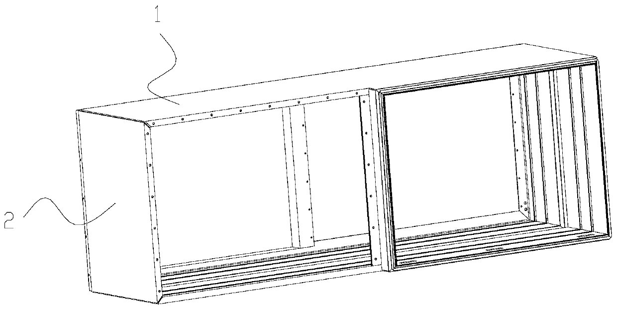
Electrical equipment box
A technology for electrical equipment boxes and boxes, which is applied in the directions of casing/cabinet/drawer components, cooling/ventilation/heating renovation, support structure installation, etc., which can solve the problem that the inside of the electrical equipment box cannot achieve a good sealing effect , Operation methods are troublesome and complicated, etc., to achieve the effect of convenient and quick installation, simple structure, and weight reduction
- Summary
- Abstract
- Description
- Claims
- Application Information
AI Technical Summary
Problems solved by technology
Method used
Image

Examples
Embodiment Construction
[0029] In the following, the present invention will be specifically described through exemplary embodiments. It should be understood, however, that elements, structures and characteristics of one embodiment may be beneficially incorporated in other embodiments without further recitation.
[0030] In the description of the present invention, it should be noted that the orientation or positional relationship indicated by the terms "inner", "outer", "upper", "lower", "front", "rear" etc. are based on the The positional relationship is only for the convenience of describing the present invention and simplifying the description, but does not indicate or imply that the referred device or element must have a specific orientation, be constructed and operated in a specific orientation, and thus should not be construed as limiting the present invention. In addition, the terms "first", "second", and "third" are used for descriptive purposes only, and should not be construed as indicating...
PUM
 Abstract
Description
Claims
Application Information