
Bicycle saddle structure

a saddle and bicycle technology, applied in the field of bicycle saddle structure, can solve the problems of saddle not providing a stable point of application to the rider during high-speed riding, rider discomfort, and saddle discomfort, and achieve the effect of improving the discomfort of an ordinary nose-shaped saddle and providing a stable point of application to the rider

Inactive Publication Date: 2016-08-09
NAN KAI UNIV TECH
View PDF24 Cites 6 Cited by
  • Summary
  • Abstract
  • Description
  • Claims
  • Application Information

AI Technical Summary

Benefits of technology

[0007]The primary objective of the present invention is to provide a bicycle saddle structure that can improve the discomfort of an ordinary nose-shaped saddle during riding and can provide a stable point of application to the rider when changing to the saddle without nose portion.
[0011]Since the nose portion is pivoted to the saddle portion via the pivoting unit, the nose portion can be selectively fixed to different positions, the saddle can be changed to the nose-shaped saddle or the saddle without nose portion, so as to improve the applicability. The elastic supporting bodies which are disposed on the bottom surface of the saddle body can provide a buffer force to the rider, so as to improve the riding comfort.

Problems solved by technology

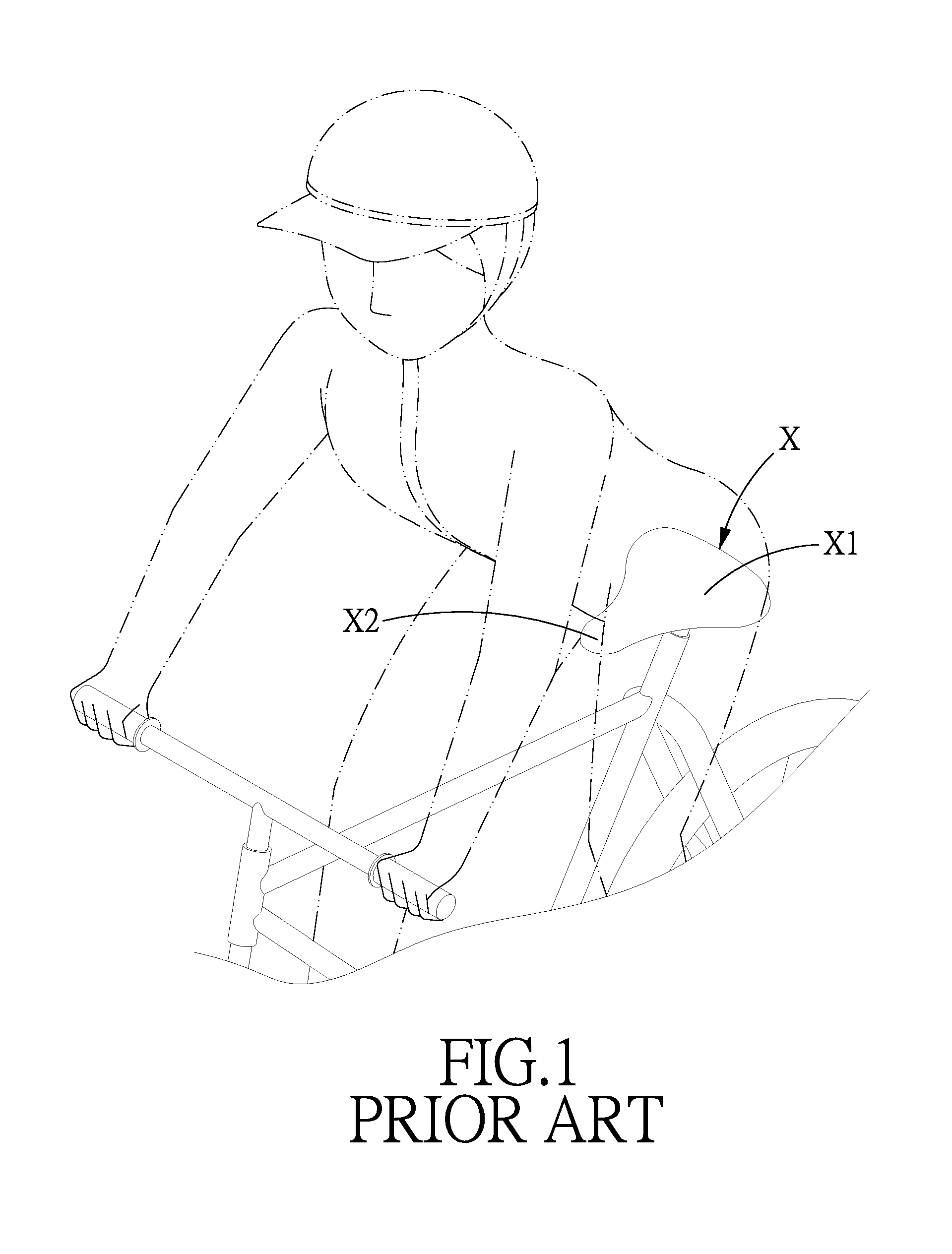
However, the seat portion X1 has no buffer parts, which will cause the rider discomfort during long time riding or when riding on the bumpy road.
In addition, although the nose portion X2 provides stable supporting points to the feet of the rider, the nose portion X2 will become an obstacle to the feet during slow riding, which will also cause the rider discomfort.
In order to overcome these problems, another conventional bicycle saddle without nose portion is developed, however, such a saddle cannot provide a stable point of application to the rider during high speed riding.
It is thus obvious that the above-mentioned saddles cannot meet the needs of different riders, the rider has to replace different kinds of saddles according to different requirements, which is inconvenient and will cause extra costs.

Method used


Image

  • Bicycle saddle structure
  • Bicycle saddle structure
  • Bicycle saddle structure

Examples


Embodiment Construction

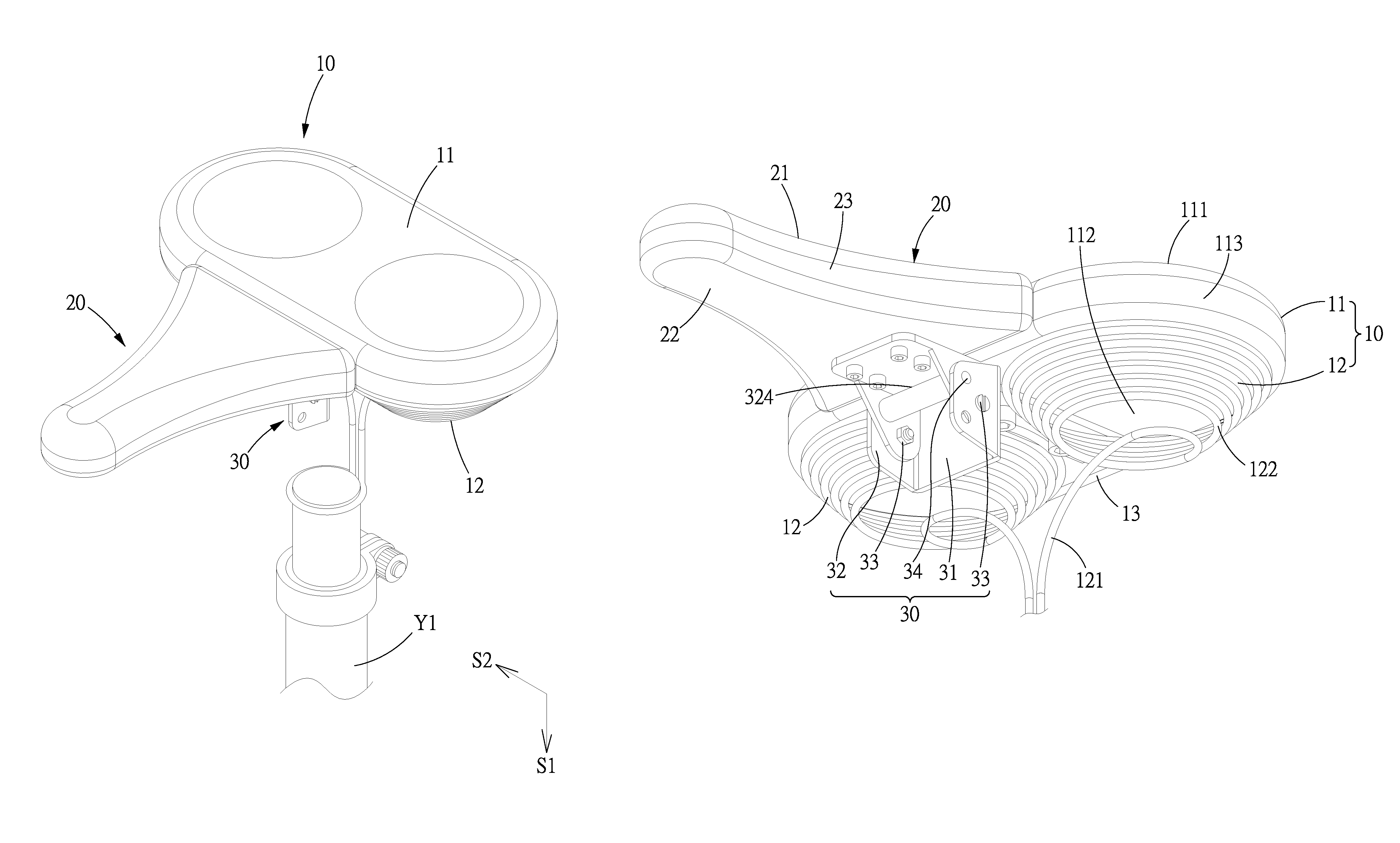
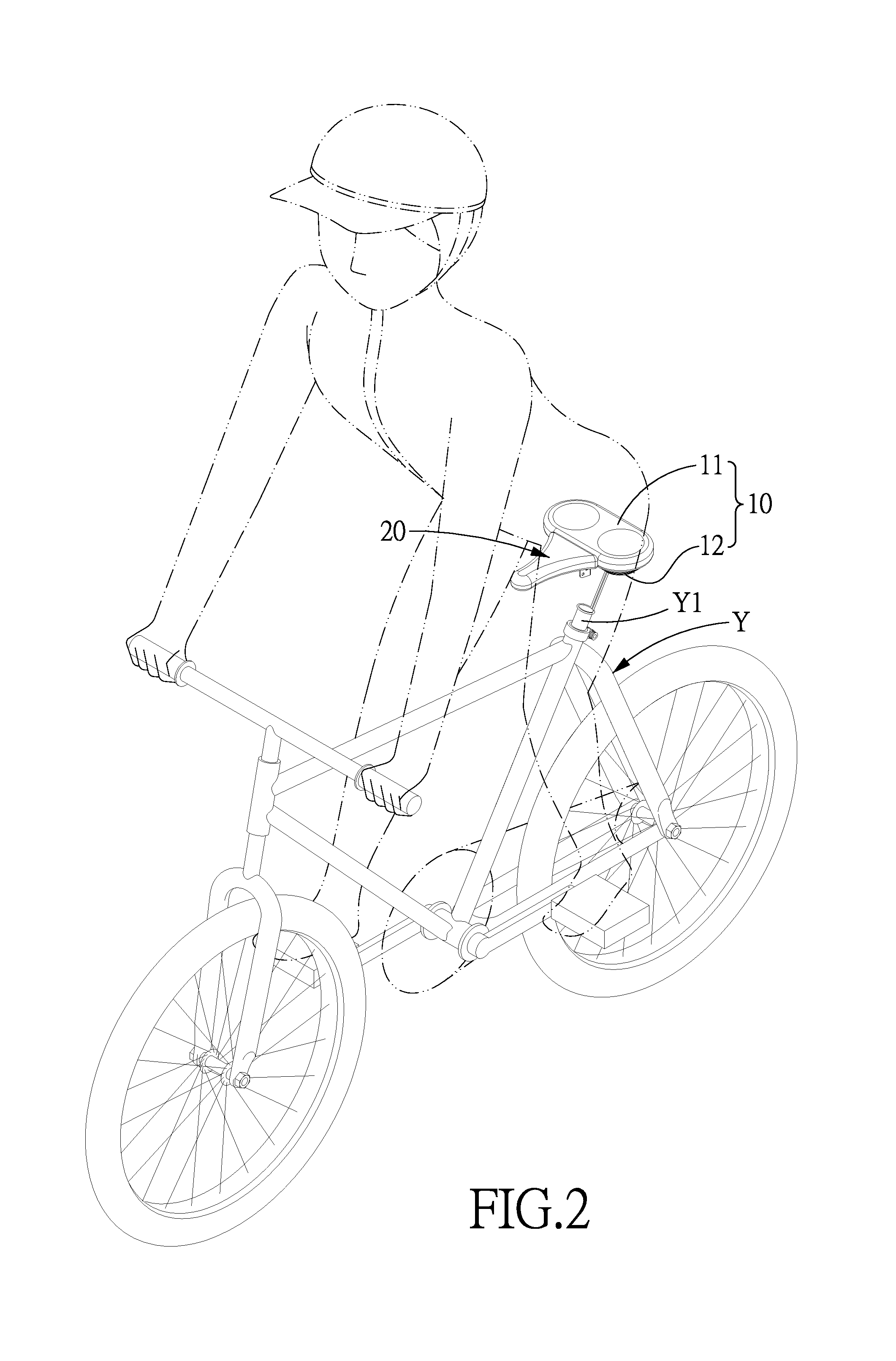
[0030]Referring to FIGS. 2-17, a bicycle saddle structure in accordance with the present invention comprises a saddle body 10 and a nose portion 20.

[0031]The saddle body 10 is connected to a seat post Y1 of a bicycle Y and is provided with a saddle portion 11 and two circular spiral elastic supporting bodies 12. The saddle portion 11 has a top surface 111 and an opposite bottom surface 112, between the top surface 111 and the bottom surface 112 is provided a lateral surface 113. The elastic supporting bodies 12 are disposed on the bottom surface 112 and are located adjacent to each other. Each elastic supporting body 12 is formed by an extension portion 121 and an elastic portion 122 formed at one end of the extension portion 121. The extension portion 121 is extended along a vertical direction S1, and a horizontal direction S2 is vertical to the vertical direction S1. The elastic portion 122 is a spiral cone structure enlarged from the extension portion 121 gradually, and the spira...


PUM


Abstract

A bicycle saddle structure includes a saddle portion having two elastic supporting bodies in a bottom surface thereof and a nose position pivoted to the saddle portion, the elastic supporting bodies are circular spiral-shaped, which can provide a buffer force to the rider, so as to improve the riding comfort. The nose portion can be selectively located at the same level as or vertical to the saddle portion via a pivoting unit, the saddle can be changed to the nose-shaped saddle or the saddle without nose portion, so as to improve the applicability.

Description

BACKGROUND OF THE INVENTION[0001]1. Field of the Invention[0002]The present invention relates to a bicycle saddle structure, and more particularly to a bicycle saddle and a bicycle seat.[0003]2. Description of the Prior Art[0004]Bicycles are often used as transportation, leisure or fitness purposes. As a means of transportation without extra energy consumption, the bicycle has a green, environmentally friendly transportation title. The rider can enjoy the surrounding scenery during slow riding, achieving leisure and pressure releasing effects. In addition, a sporty bicycle can achieve the fitness purpose through high speed riding.[0005]Referring to FIG. 1, a conventional nose-shaped bicycle saddle X comprises a seat portion X1 and a nose portion X2 forwardly protruded out of a center of the seat portion X1, the seat portion X1 is used to support the rider's hips. However, the seat portion X1 has no buffer parts, which will cause the rider discomfort during long time riding or when r...

Claims


Application Information

Patent Timeline
Patent Type & Authority Patents(United States)
IPC IPC(8): B62J1/00B62J1/04B62J1/08B62J1/02
CPCB62J1/04B62J1/08B62J1/007B62J1/02B62J1/005
Inventor CHANG, TENG-RUEY
Owner NAN KAI UNIV TECH
Learn More