Connecting rod construction

A connecting rod and structure technology, applied in medical science, internal bone synthesis, internal fixator, etc., can solve problems such as failure to supply, damage to the surrounding cells and tissues of the spine, and poor stability of implanted bone nails, etc.

Inactive Publication Date: 2012-05-30
TOPASIA INT TECH INC
View PDF4 Cites 8 Cited by
  • Summary
  • Abstract
  • Description
  • Claims
  • Application Information

AI Technical Summary

Problems solved by technology

However, because the formation and combination angles of each vertebrae in the human body are different, the rigid fixation rod structure installed in the aforementioned surgery has no elastic space for any angle at all for the curvature of the human spine. Afterwards, the mobility is greatly restricted and severe discomfort is caused, especially for patients with osteoporosis, this rigid fixation rod structure often leads to poor consolidation and stability of the implanted bone screws The problem is that the bone nails will loosen or fall off, and will even damage the vertebrae and its surrounding tissue; in addition, the rigid fixation rod structure will make the original joints lose their function, causing the upper and lower joints to assume the functions of the original joints. And it cannot provide the flexibility and cushioning function of the intervertebral disc, so it is easy to cause premature aging or damage of the upper and lower vertebral joints due to overuse, and it is really necessary to improve

Method used


Image

  • Connecting rod construction
  • Connecting rod construction
  • Connecting rod construction

Examples


Embodiment Construction

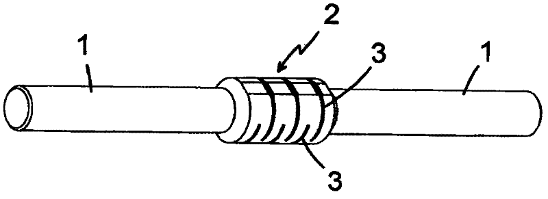
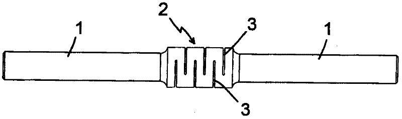
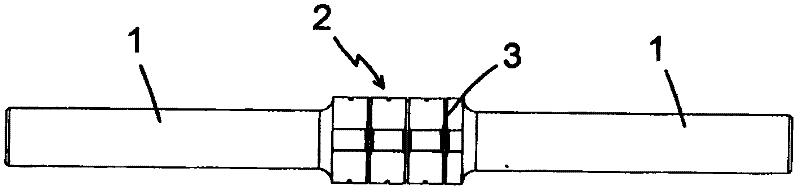
[0022] Such as Figure 1 to Figure 3 Shown is a preferred embodiment of the present invention, which is provided with an elastic portion 2 in the middle of the connecting rod 1; the connecting rod 1 is a slightly cylindrical rod, and the elastic portion 2 is located The middle section of the elastic part is a short cylinder with a thicker outer diameter, and several radial hollow grooves 3 are arranged on the upper and lower sides of the elastic part, and the radial hollow grooves on the two sides are arranged to be in the direction of each other. In this embodiment, the elastic part 2 is integrally formed on the rod column of the connecting rod 1, and the connecting rod and the elastic part are made of titanium alloy material, because the material has good Mechanical strength and chemical resistance, so it is suitable for use between the human spine; usually the width of the hollow groove 3 of the aforementioned elastic part is set between 0.08mm-1.2mm, and the depth of the g...


PUM


Abstract

The invention relates to a connecting rod construction. One or more than one elastic element is arranged on a connecting rod, and each elastic element is provided with one or more than one hollow slot, wherein the hollow slots on each elastic element are arranged at a bending side and / or an opposite side of the bending side, and when the hollow slots are arranged at the two opposite sides of each elastic element, the hollow slots are respectively arranged at the two opposite sides of the elastic element in an interval staggered manner; and the hollow slots of the elastic element are utilized, thus a gap space of the hollow slot can stretch out and draw back correspondingly when the connecting rod is under stress, elastic deformability of the connecting rod is improved, and the connecting rod can have the functions of bending, twisting, compressing, stretching, absorbing and buffering oscillation.

Description

technical field [0001] The present invention relates to a connecting rod structure, in particular to a connecting rod structure used for locked connection between a plurality of bone nails nailed on the vertebrae, and the rod body has elastic deformation performance. Background technique [0002] Once the spine is displaced or compressed or even the surrounding muscles and ligaments are tense, it will directly affect the nerves in the spine and indirectly cause the end organs supplied by the nerves, muscles or secretory lines, resulting in inconvenient movement, pain, and physical discomfort. For this kind of symptoms, surgical methods can be used to install a fixation device between the vertebrae to achieve the effect of decompression. It is known that this kind of treatment operation is to implant and fix the bone nails in the upper and lower vertebrae respectively. position, and then lock and fix a connecting rod between the two bone nails, so that the bone nails are conn...

Claims


Application Information

Patent Timeline
Patent Type & Authority Applications(China)
IPC IPC(8): A61B17/70A61B17/68A61L31/02
CPCA61B17/7026
Inventor 颜宗宝
Owner TOPASIA INT TECH INC
Why Eureka
Try Eureka