

Electronic device and wristwatch
a technology applied in the field of electronic devices and wristwatches, can solve problems such as inability of wristwatches
- Summary
- Abstract
- Description
- Claims
- Application Information
AI Technical Summary
Benefits of technology
Problems solved by technology
Method used
Image

Examples
first embodiment
[0022]Hereinafter, a first embodiment where the present invention has been applied in a pointer type wristwatch will be described with reference to FIG. 1 to FIG. 6.
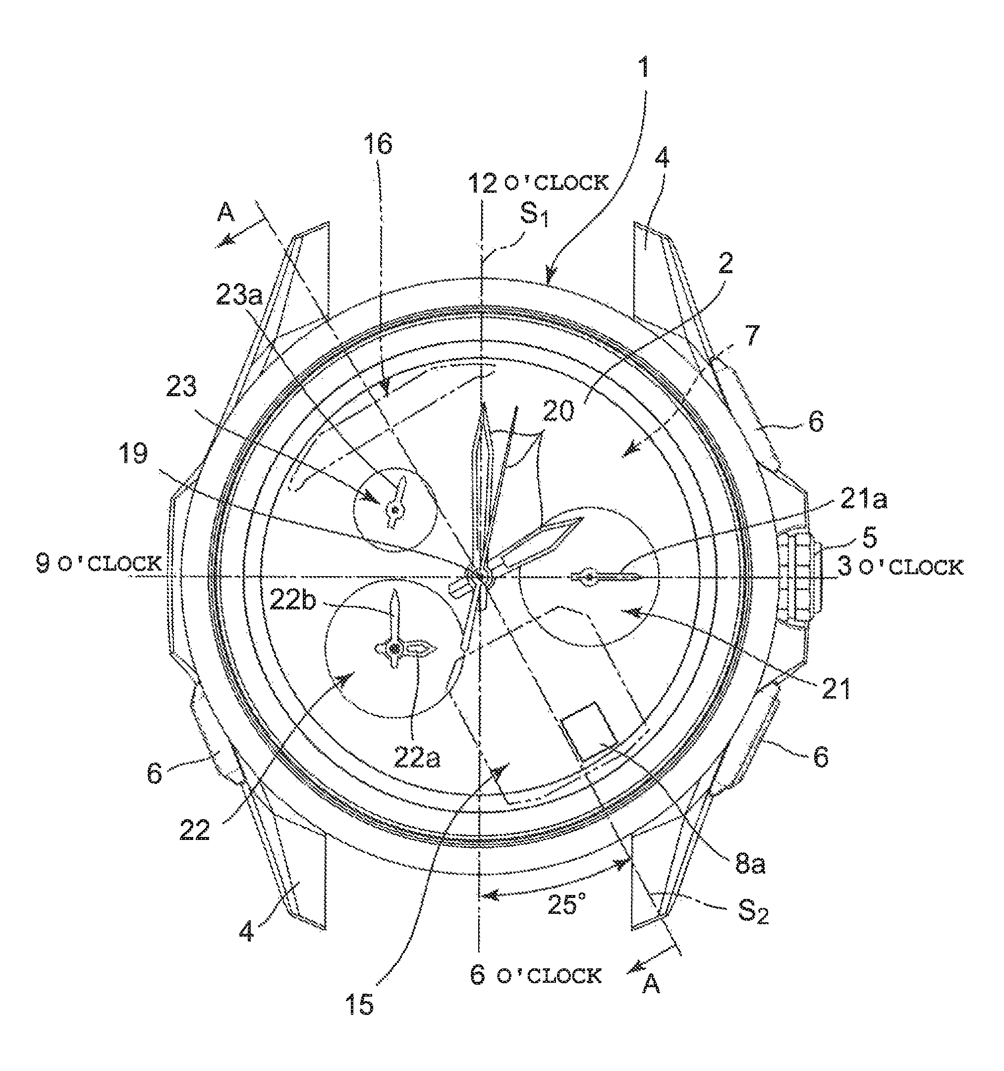
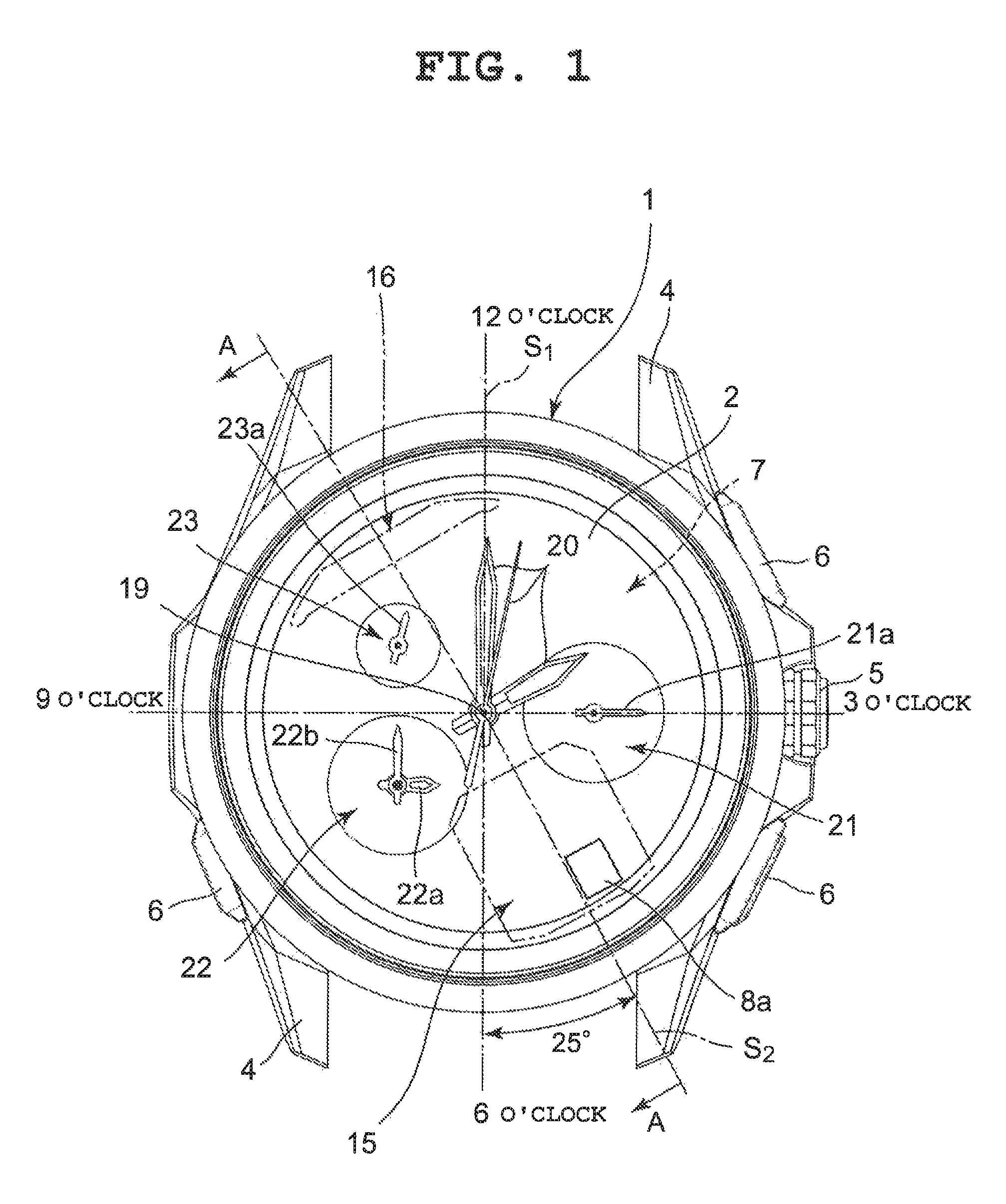
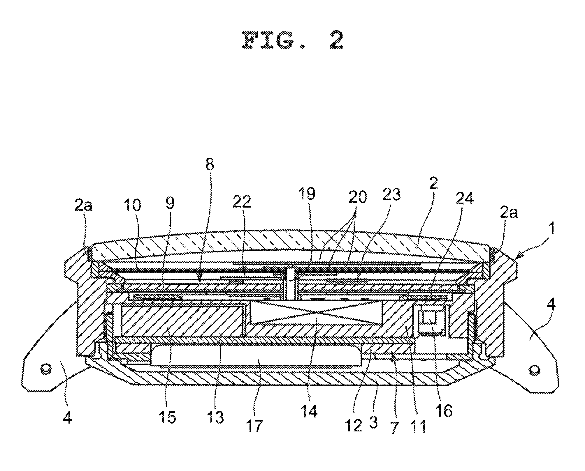
[0023]This wristwatch includes a wristwatch case 1 as shown in FIG. 1 and FIG. 2, and a watch glass 2 is attached to the upper opening portion of this wristwatch case 1 via a packing 2a. The lower portion of this wristwatch case 1 has a rear lid 3 attached thereto.
[0024]On the six o'clock side and the twelve o'clock side of the outside surface of this wristwatch case 1, band attaching sections 4 are provided, respectively, as shown in FIG. 1 and FIG. 2. Also, this wristwatch case 1 has a crown 5 provided on its side surface on the three o'clock side and push-button switches 6 provided on its side surfaces on the two o'clock side, the four o'clock side, and the eight o'clock side, respectively.
[0025]Inside this wristwatch case 1, a timepiece module 7 is mounted as shown in FIG. 2, and a dial plate 8 is arranged above the ...
second embodiment
[0089]Next, a second embodiment in which the present invention has been applied in a pointer type wristwatch is described with reference to FIG. 10. Note that sections identical to those in the first embodiment shown in FIG. 1 to FIG. 6 are provided with the same reference numerals.
[0090]The structure of this wristwatch is the same as that of the first embodiment except the arrangement positions of the first antenna 15 and the second antenna 16 and the arrangement positions of the first sub-display section 21, the second sub-display section 22, and the third sub-display section 23.
[0091]Specifically, the first antenna 15 is arranged on the twelve o'clock side of the timepiece module 7 and the second antenna 16 is arranged on the six o'clock side of the timepiece module 7 opposing the first antenna 15, as shown in FIG. 10. In this embodiment as well, the first antenna 15 and the second antenna 16 are arranged opposing each other within an angle range of about 100 degrees formed by th...
third embodiment
[0107]Next, a third embodiment in which the present invention has been applied in a pointer type wristwatch is described with reference to FIG. 11. In this embodiment as well, sections identical to those in the first embodiment shown in FIG. 1 to FIG. 6 are provided with the same reference numerals.
[0108]The structure of this wristwatch of the third embodiment is the same as that of the first embodiment except the arrangement positions of the first antenna 15 and the second antenna 16 and the arrangement positions of the first sub-display section 21, the second sub-display section 22, and the third sub-display section 23.
[0109]Specifically, the first antenna 15 is arranged on the twelve o'clock side of the timepiece module 7 and the second antenna 16 is arranged on the six o'clock side of the timepiece module 7 opposing the first antenna 15, as shown in FIG. 11. In this embodiment as well, the first antenna 15 and the second antenna 16 are arranged opposing each other within an angl...
PUM
 Abstract
Description
Claims
Application Information