
HVAC controller having integrated comfort window display

a comfort window display and hvac controller technology, applied in ventilation systems, heating types, instruments, etc., can solve the problems of increasing the complexity of modern hvac controllers, difficult programming and/or operating such devices, and difficult interaction with the user interfa

Active Publication Date: 2016-08-23
BRUCE BRADLEY STEVE +1
View PDF17 Cites 21 Cited by
  • Summary
  • Abstract
  • Description
  • Claims
  • Application Information

AI Technical Summary

Benefits of technology

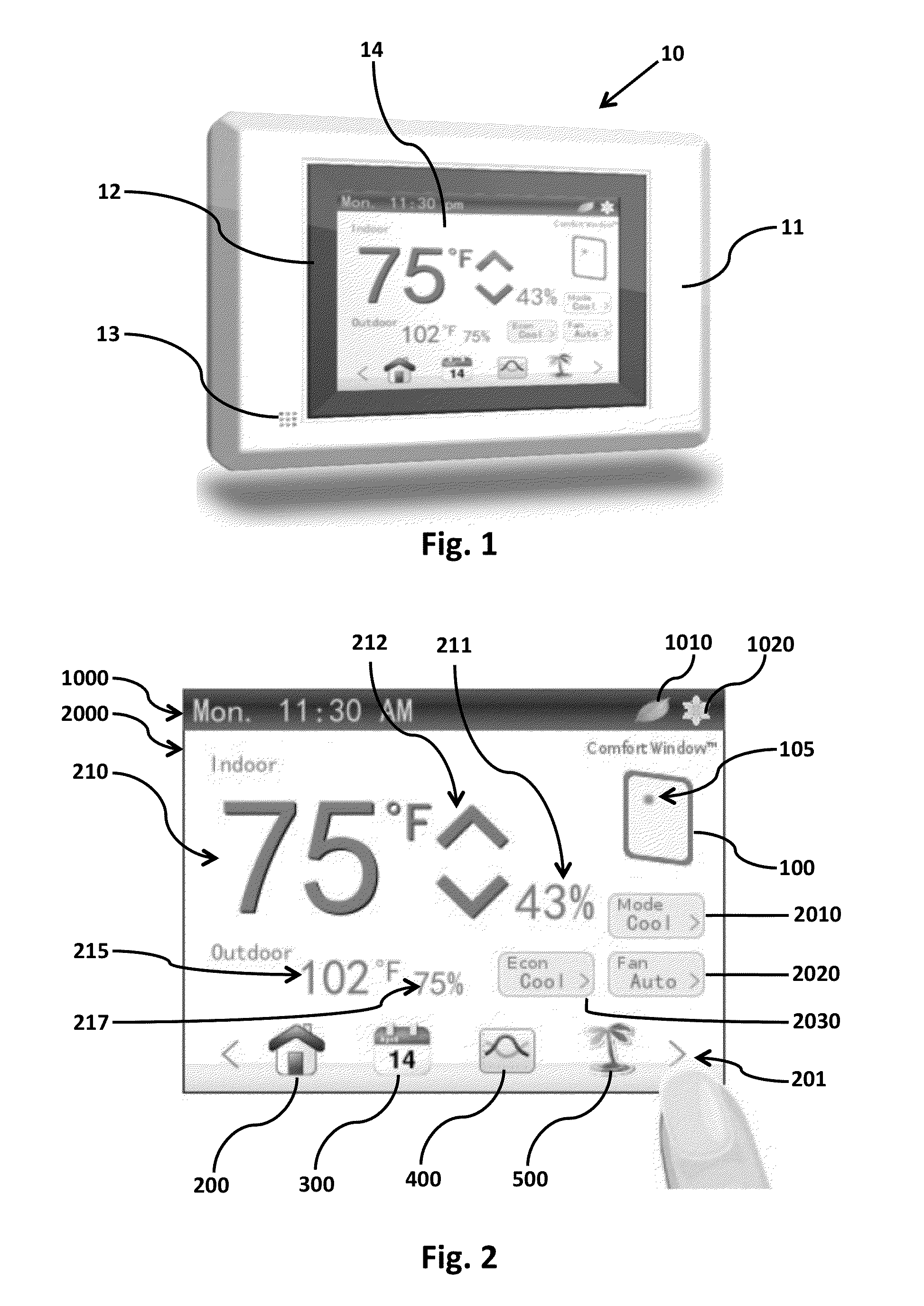
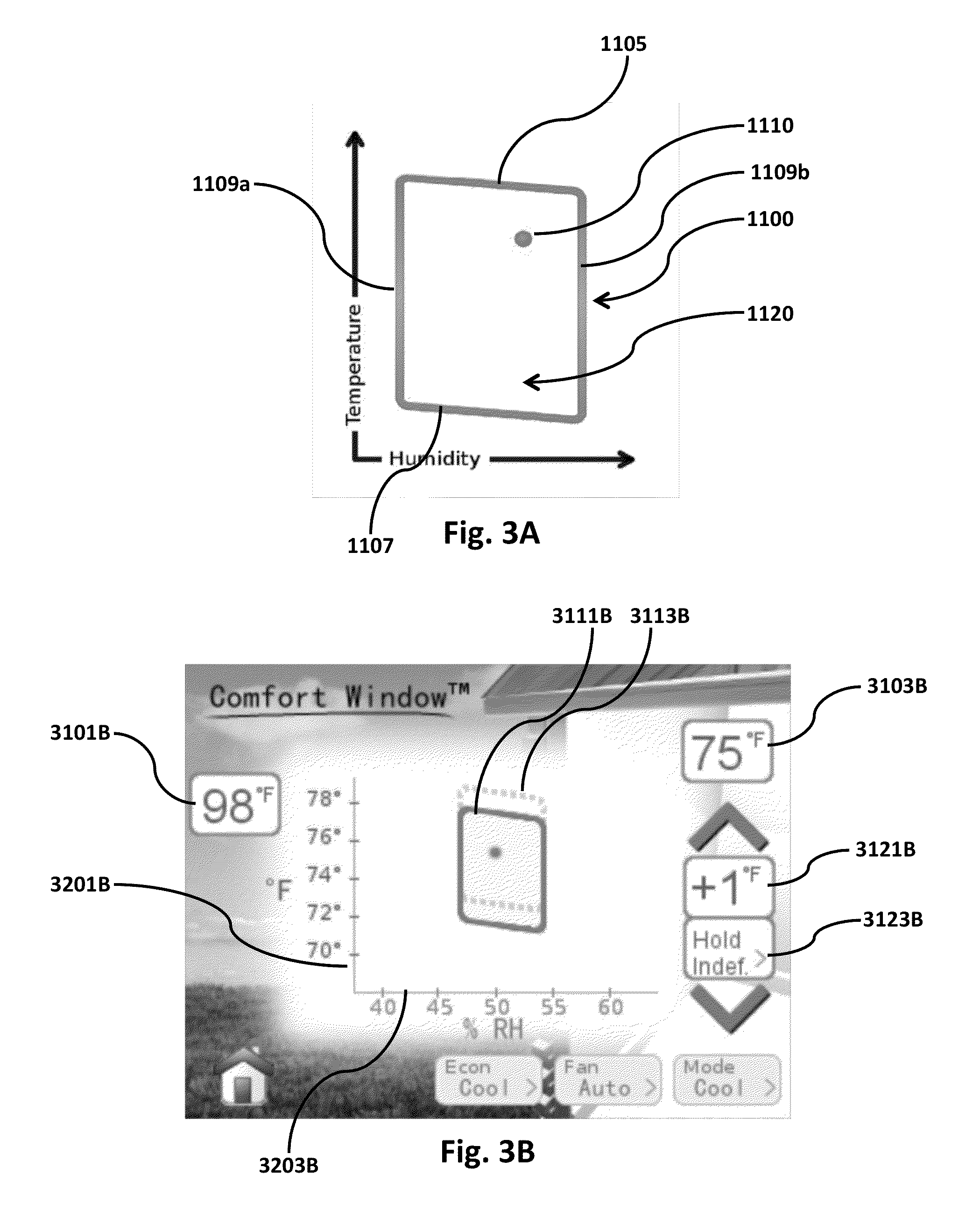
The present invention provides a device and method for controlling a HVAC system that is more intuitive and user-friendly. The device includes a display and controller that receives user-defined environmental settings and detects environmental conditions through sensors. The controller then displays the detected conditions on the screen in a visual representation of the user's comfort level, with borders representing the user's settings. The method also involves programming and controlling the HVAC system based on the received and programmed environmental conditions. Overall, the invention simplifies the process for controlling the HVAC system and allows for improved user satisfaction.

Problems solved by technology

Interaction with the user interface can often prove difficult, discouraging many users from attempting to program the controller to run on a schedule, viewing how the controller is operating within preset parameters, or observing the controller's efficiency or when it is conserving energy.
The increased complexity of such modern HVAC controllers, programming and / or operating such devices can be considered difficult and / or confusing, particularly for novice and / or non-technical users.

Method used


Image

  • HVAC controller having integrated comfort window display
  • HVAC controller having integrated comfort window display
  • HVAC controller having integrated comfort window display

Examples


Embodiment Construction

[0032]Phrases and terms similar to “software”, “application”, “algorithm”, and “firmware” may include any non-transitory computer readable medium storing thereon a program, which when executed by a computer, causes the computer to perform a method or function.

[0033]Phrases and terms similar to “network” may include one or more data links that enable the transport of electronic data between computer systems and / or modules. When information is transferred or provided over a network or another communications connection (either hardwired, wireless, or a combination of hardwired or wireless) to a computer, the computer uses that connection as a computer-readable medium. Thus, by way of example, and not limitation, computer-readable media can also comprise a network or data links which can be used to carry or store desired program code in the form of computer-executable instructions or data structures and which can be accessed by a general purpose or special purpose computer.

[0034]Phrases...


PUM


Abstract

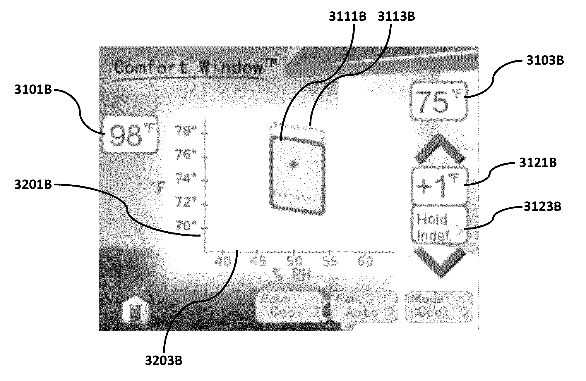
A device configured to control one or more components of an HVAC system. The device includes a display, a controller in communication with the display, and wherein the controller is configured to receive one or more user defined environmental settings. Further, the controller communicates with one or more environmental sensors, wherein the environmental sensors detect one or more environmental conditions. In addition, the controller is further configured to provide a visual indication on the display for the detected environmental conditions with respect to the user defined environmental settings. This visual indication includes one or more bounded region having an interior space indicative of user comfort level, wherein the bounded regions have one or more borders, and wherein the borders at least partially represent the user defined environmental settings. In addition, the visual indication includes one or more icons that represents the detected environmental conditions and are displayed in relation to the bounded regions.

Description

FIELD OF THE INVENTION[0001]A user friendly HVAC controller that allows a user to dynamically, graphically, and visually view current comfort conditions, set comfort settings such as temperature and humidity, and control comfort conditions, among other features.BACKGROUND[0002]Heating, ventilation, and / or air conditioning (HVAC) systems are often used to control the comfort level within a building or other structure. Many HVAC systems include a controller that activates and deactivates one or more HVAC components of the HVAC system to affect and control one or more environmental conditions within the building. These environmental conditions can include, but are not limited to, temperature, humidity, and / or ventilation. In many cases, such HVAC controllers may include, or have access to, one or more environmental sensors, and may use parameters provided by the one or more sensors to control the one or more HVAC components to achieve desired programmed or set environmental conditions....

Claims


Application Information

Patent Timeline
Patent Type & Authority Patents(United States)
IPC IPC(8): G05B13/00F24F3/14G05D27/02F24F7/00G08B23/00G08C15/06G05D22/02G05D23/19G05D23/00G05B15/00F24F11/00
CPCF24F11/0086G05D22/02G05D23/1902G05D27/02F24F11/0012F24F11/0015F24F11/0017F24F2011/0064F24F2011/0075Y02B30/78F24F11/30F24F2110/10F24F2110/20F24F2110/50F24F11/65F24F11/46Y02B30/70F24F11/52
Inventor BRUCE, BRADLEY STEVEWALTER, DANIEL JAMES
Owner BRUCE BRADLEY STEVE
Learn More