
Optimizing drag field voltages in a collision cell for multiple reaction monitoring (MRM) tandem mass spectrometry

a technology of tandem mass spectrometry and collision cell, which is applied in the direction of spectrometer combinations, electric discharge tubes, particle separator tubes, etc., can solve the problems of significant performance compromise, insufficient time of collision cells (qsub>2/sub>), and particularly problematic cross-talk effects

Active Publication Date: 2016-08-23
THERMO FINNIGAN
View PDF13 Cites 1 Cited by
  • Summary
  • Abstract
  • Description
  • Claims
  • Application Information

AI Technical Summary

Benefits of technology

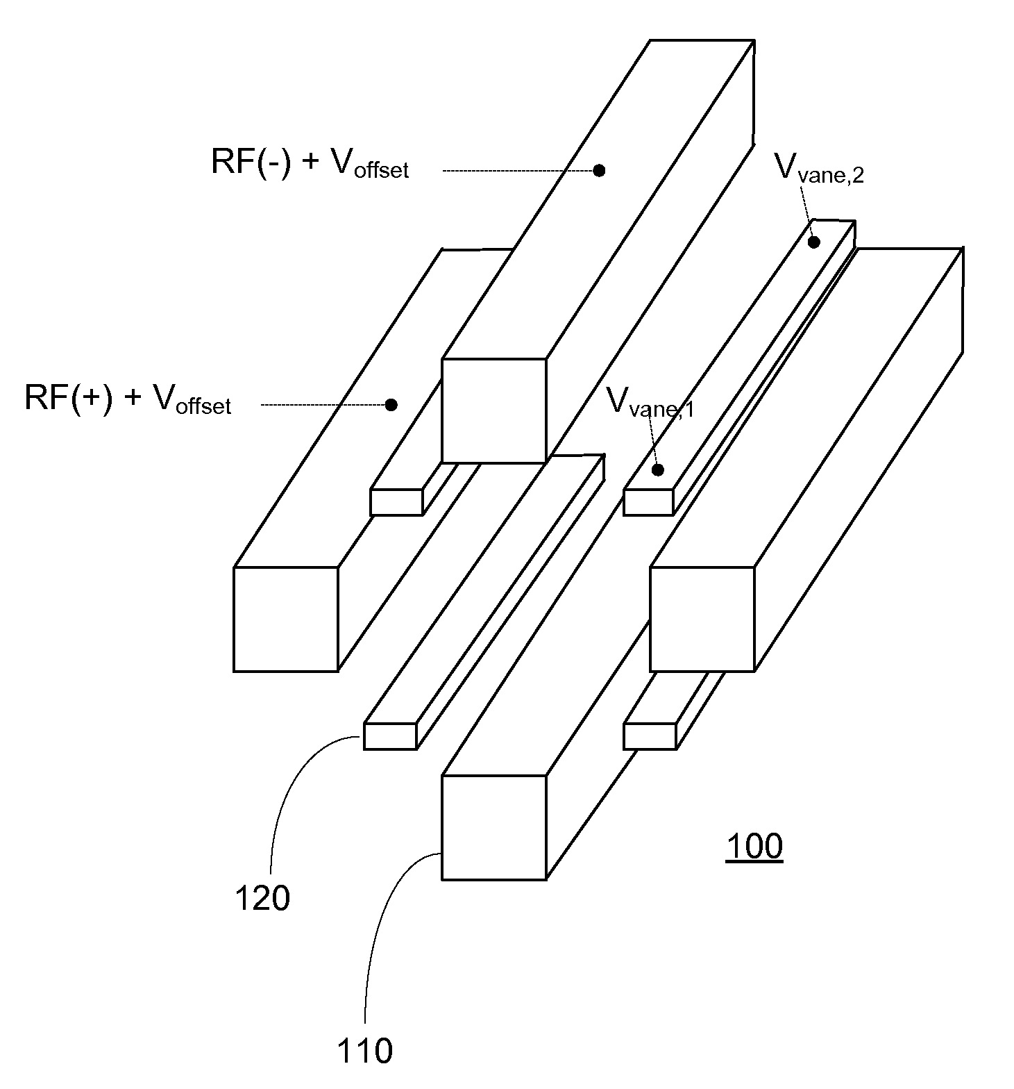
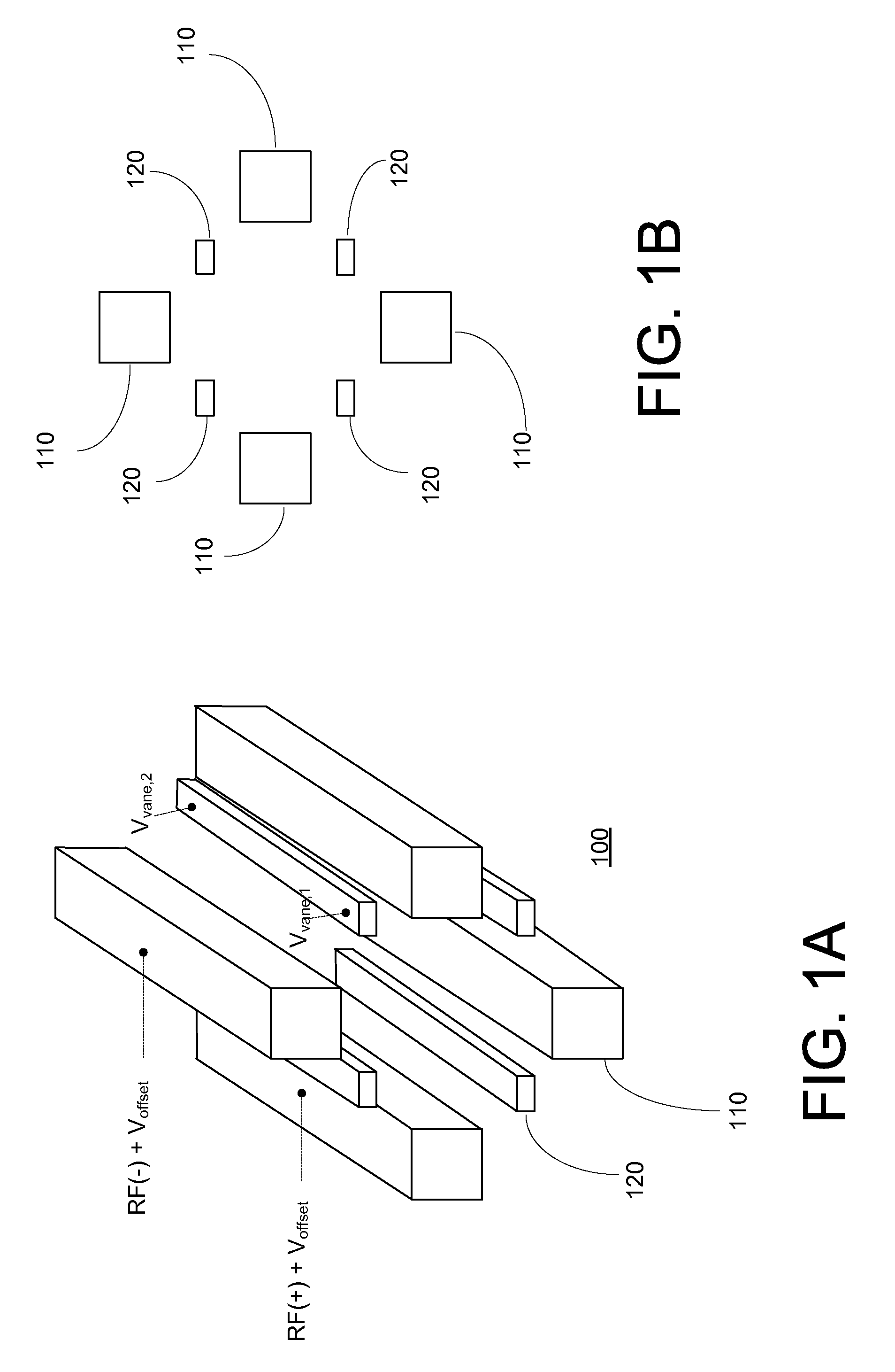
The patent describes a collision cell used in mass spectrometry that has rod electrodes and drag vanes arranged in a square pattern around an axial centerline. The method includes applying an offset voltage to the rod electrodes and adjusting the voltages applied to the drag vanes to identify the vane that produces the maximum intensity of a transition. The method also involves adjusting the drag field to minimize cross-talk with other transitions. The technical effect of this invention is to improve the accuracy and sensitivity of mass spectrometry by optimizing the performance of the collision cell.

Problems solved by technology

It is known that the phenomenon of cross-talk may significantly compromise performance when a triple quadrupole mass spectrometer is operated at high MRM rates.
Due to the high MRM rate, the collision cell (Q2) may not have sufficient time to clear the product ions from the first transition before switching to the second transition.
The cross-talk effect can be particularly problematic if the ions corresponding to the first transition are of high intensity, as it can lead to more plausible false positives on the subsequent transition.

Method used


Image

  • Optimizing drag field voltages in a collision cell for multiple reaction monitoring (MRM) tandem mass spectrometry
  • Optimizing drag field voltages in a collision cell for multiple reaction monitoring (MRM) tandem mass spectrometry
  • Optimizing drag field voltages in a collision cell for multiple reaction monitoring (MRM) tandem mass spectrometry

Examples


Embodiment Construction

[0049]Embodiments of systems and methods for operating a collision cell of a triple quadrupole mass spectrometer are described herein.

[0050]The section headings used herein are for organizational purposes only and are not to be construed as limiting the described subject matter in any way.

[0051]In this detailed description of the various embodiments, for purposes of explanation, numerous specific details are set forth to provide a thorough understanding of the embodiments disclosed. One skilled in the art will appreciate, however, that these various embodiments may be practiced with or without these specific details. In other instances, structures and devices are shown in block diagram form. Furthermore, one skilled in the art can readily appreciate that the specific sequences in which methods are presented and performed are illustrative and it is contemplated that the sequences can be varied and still remain within the spirit and scope of the various embodiments disclosed herein.

[0...


PUM


Abstract

A collision cell has a plurality of rod electrodes arranged in opposed pairs around an axial centerline and a plurality of drag vanes arranged in the interstitial spaces between the rod electrodes. Operating the collision cell includes, applying a rod offset voltage to the rod electrodes, and varying an offset voltage applied to the drag vanes to identify a vane offset voltage with a maximum intensity for the transition. The method further includes varying a drag field by adjusting the voltages applied to drag vane terminals in opposite directions to identify a drag field value with a cross talk below a cross talk threshold, varying the vane offset voltage by adjusting the voltages applied to the drag vane terminals to maximize the intensity of the transition while preserving the drag field, and operating the collision cell at the vane offset voltage and drag field to monitor the transition.

Description

INTRODUCTION[0001]The present invention relates generally to triple quadrupole mass spectrometers, and more particularly to a method of operating a collision cell of a triple quadrupole mass spectrometer to minimize crosstalk in multiple reaction monitoring (MRM) mode.BACKGROUND OF THE INVENTION[0002]Triple quadrupole mass spectrometers are used widely for the analysis of a variety of substances. As the name denotes, triple quadrupole mass spectrometers include three quadrupole structures for mass analysis: a first quadrupole (also referred to as a quadrupole mass filter, or QMF) that selectively transmits precursor ions having a specified mass-to-charge ratio (m / z), a second quadrupole positioned within a gas-filled enclosure (referred to as a collision cell) for receiving the precursor ions transmitted through the first resolving quadrupole and causing the ions to undergo fragmentation into product ions, and a third quadrupole that receives the product ions from the second quadrup...

Claims


Application Information

Patent Timeline
Patent Type & Authority Patents(United States)
IPC IPC(8): H01J49/42H01J49/00
CPCH01J49/005H01J49/429H01J49/4225H01J49/4215
Inventor SILIVRA, OLEGOSER, HARALDMAZE, JOSHUA T.OLNEY, TERRYSCHOEN, ALAN E.
Owner THERMO FINNIGAN
Learn More