Optic modulator and method of manufacturing the same
a technology of optical modulator and modulator, which is applied in the direction of optical elements, liquid/fluent solid measurement, instruments, etc., can solve the problems of shortening the service life and affecting the efficiency of the p-i-n diode structure, so as to achieve the effect of effectively modulating, small influence on the optical confinement factor, and rapid response characteristi
- Summary
- Abstract
- Description
- Claims
- Application Information
AI Technical Summary
Benefits of technology
Problems solved by technology
Method used
Image
Examples
first embodiment
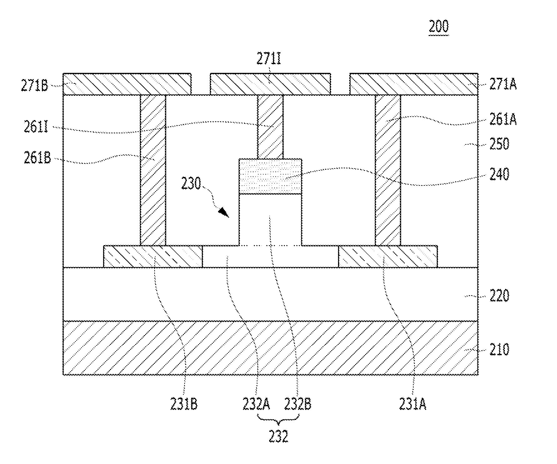
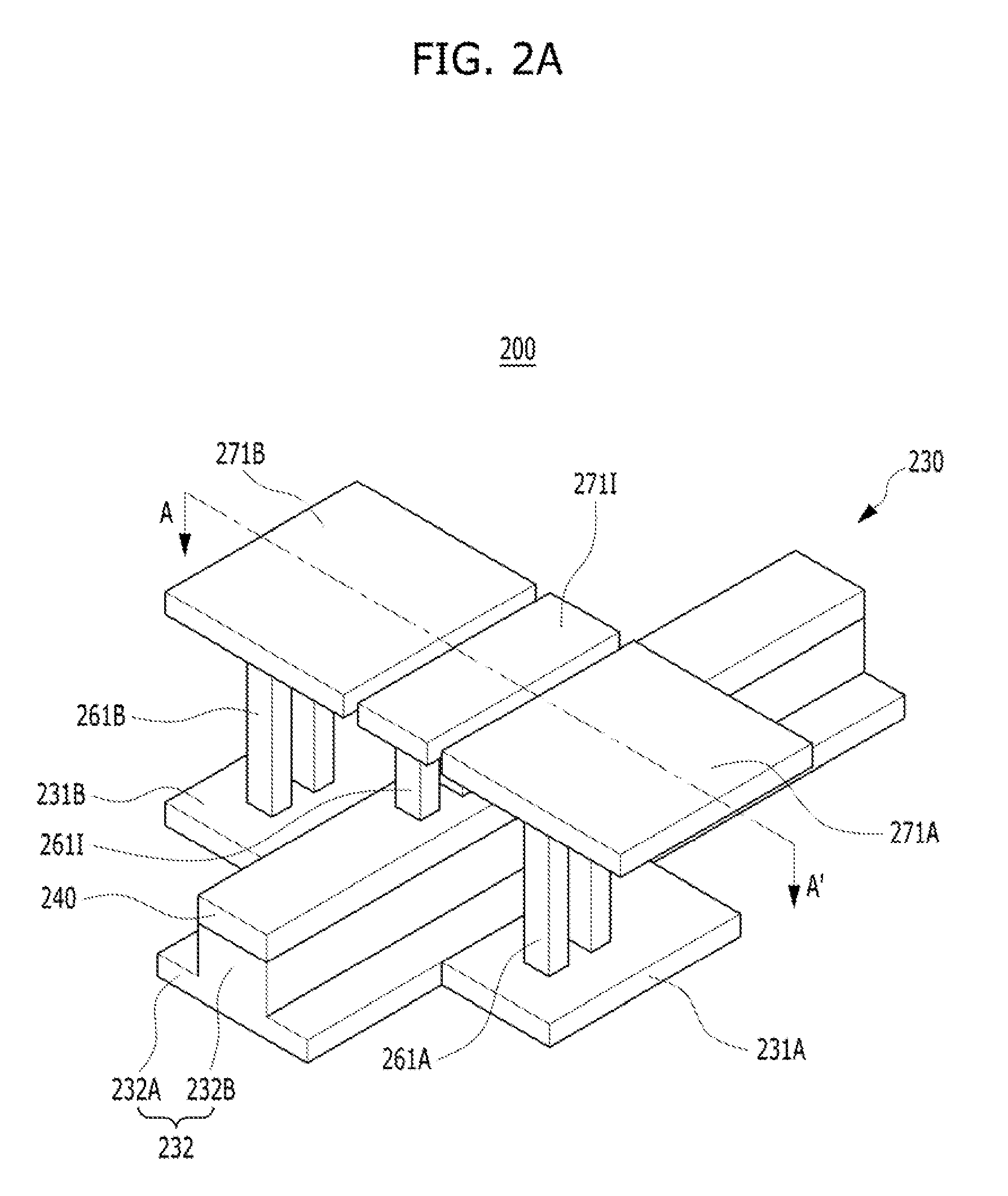
[0029]FIG. 2A is a perspective view of an optic modulator in accordance with a FIG. 2B is a cross-sectional view of the optic modulator, taken along like A-A′ of FIG. 2A.
[0030]Referring to FIGS. 2A and 2B, the optic modulator 200 in accordance with the present embodiment may be formed over a semiconductor substrate 210. The semiconductor substrate 210 may include a material suitable for semiconductor processing. The semiconductor substrate 210 may contain silicon. For example, the semiconductor substrate 210 may include a silicon substrate. In another embodiment, the semiconductor substrate 210 may include a single-crystal silicon substrate. The semiconductor substrate 310 may include a SiGe substrate. The semiconductor substrate 210 may include a compound semiconductor such as GaAs or InP.
[0031]An insulating layer 220 may be formed over the semiconductor substrate 210. The insulating layer 220 may include silicon oxide. The insulating layer 220 may be formed through oxidation or d...
second embodiment
[0043]FIG. 3 is a diagram illustrating an optic modulator in accordance with a
[0044]In the present embodiment, the optic modulator 300 may be formed over a semiconductor substrate 310. The semiconductor substrate 310 may include a material suitable for semiconductor processing. The semiconductor substrate 310 may contain silicon. For example, the semiconductor substrate 310 may include a silicon substrate. In another embodiment, the semiconductor substrate 310 may include a single-crystal silicon substrate. The substrate 310 may include a SiGe substrate. The semiconductor substrate 310 may include a compound semiconductor such as GaAs or InP.
[0045]An insulating layer 320 may be formed over the semiconductor substrate 310. The insulating layer 320 may include silicon oxide. The insulating layer 320 may be formed through oxidation or deposition. The insulating layer 320 may serve to optically separate the semiconductor substrate 310 and an optical waveguide 230 from each other. Thus, ...
third embodiment
[0060]FIG. 4 is a diagram illustrating an optic modulator in accordance with a
[0061]The third embodiment does not disclose an optic modulator having a Schottky diode structure, but discloses an optic modulator using a metal-insulator-semiconductor capacitor structure.
[0062]In the present embodiment, the optic modulator 400 may be formed over a semiconductor substrate 410. The semiconductor substrate 410 may include a material suitable for semiconductor processing. The semiconductor substrate 410 may contain silicon. For example, the semiconductor substrate 410 may include a silicon substrate. In another embodiment, the semiconductor substrate 410 may include a single-crystal silicon substrate. The substrate 410 may include a SiGe substrate. The semiconductor substrate 410 may include a compound semiconductor such as GaAs or InP.
[0063]An insulating layer 420 may be formed over the semiconductor substrate 410. The insulating layer 420 may include silicon oxide. The insulating layer 42...
PUM
| Property | Measurement | Unit |
|---|---|---|
| thickness | aaaaa | aaaaa |
| height | aaaaa | aaaaa |
| width | aaaaa | aaaaa |
Abstract
Description
Claims
Application Information
 - R&D
- Intellectual Property
- Life Sciences
- Materials
- Tech Scout
- Unparalleled Data Quality
- Higher Quality Content
- 60% Fewer Hallucinations
Browse by: Latest US Patents, China's latest patents, Technical Efficacy Thesaurus, Application Domain, Technology Topic, Popular Technical Reports.
© 2025 PatSnap. All rights reserved.Legal|Privacy policy|Modern Slavery Act Transparency Statement|Sitemap|About US| Contact US: help@patsnap.com


