Resistance heating

A heating plate and heating element technology, applied in the direction of ohmic resistance heating, electric heating devices, electrical components, etc., can solve the problems that the heat carrier cannot be taken out, the fault of the heat carrier is unobtrusive, and the uneven temperature distribution, etc., to achieve simple assembly, Short post-heating times, cheap effects to produce

Inactive Publication Date: 2006-02-15
CFS GERMANY
View PDF1 Cites 3 Cited by
  • Summary
  • Abstract
  • Description
  • Claims
  • Application Information

AI Technical Summary

Problems solved by technology

However, these heat carriers have the disadvantage that an input of heat energy occurs locally, which leads to an inhomogeneous and often undesirable temperature distribution in the part to be heated, failure of the heat carrier is often unnoticed and practically Can not take out the heat carrier

Method used


Image

  • Resistance heating
  • Resistance heating
  • Resistance heating

Examples


Embodiment Construction

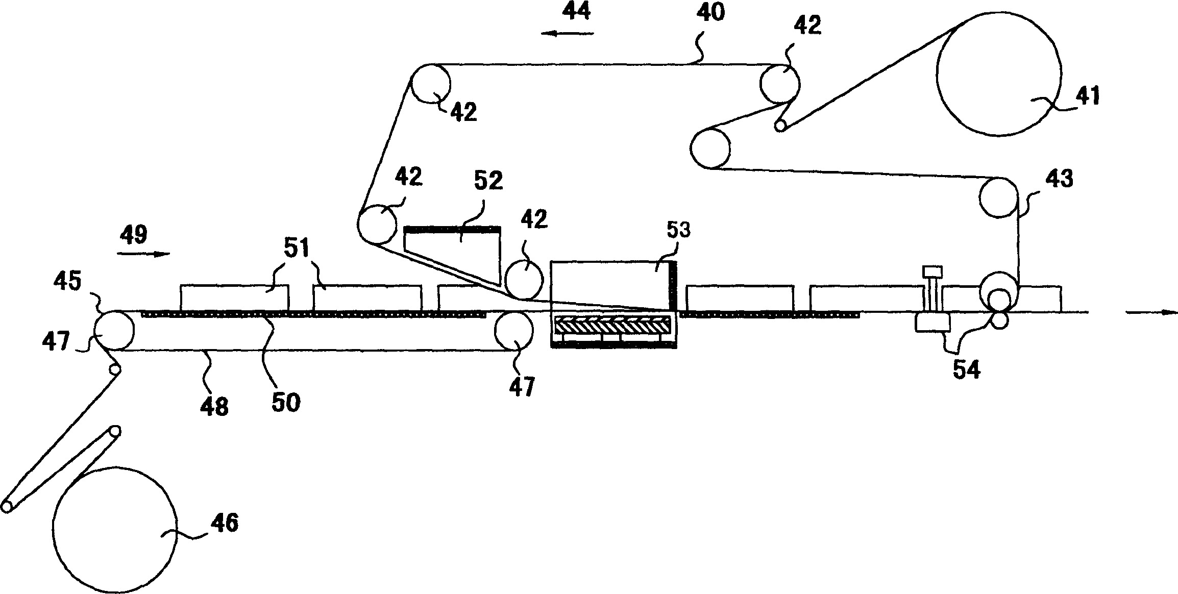
[0048] exist figure 1 In , the top web 40 is unwound from a supply roll 41 and guided on deflection pulleys 42 to individual work stations. The top web 40 is conveyed along a chain conveyor 43 which conveys the top web 40 in the direction of arrow 44 . The back web 45 is conveyed from a supply roll 46 by a chain conveyor 48 driven by a sprocket 47 in the direction of arrow 49 . The back web 45 is guided on a table 50 comprising a cooling plate and an insert formwork. The package contents 51 are then deposited on the moving back web 45 and transported with the back web 45 in the transport direction 49 to further work stations. After the package contents 51 are placed on the bottom web 45, the bottom web 45 and top web 40 are joined together once the top web 40 passes through the preheating station 52. The webs 40, 45 joined to each other, together with the package contents 51, pass through a vacuum chamber 53 formed by a fixed bottom and a lowerable top. When the package c...


PUM

PropertyMeasurementUnit
widthaaaaaaaaaa
thicknessaaaaaaaaaa
heightaaaaaaaaaa

Abstract

The desired temperature distribution is promoted in the second molding (5) by selection of the material, geometry and arrangement of the electrically-conducting bridge (2). An Independent claim is included for the method of heating.

Description

technical field [0001] The invention relates to a tool in a packaging machine comprising, as a heating element, a first shaped part, preferably a plate, with at least one conductive track of any desired length. The invention also relates to a method of heating the tool or film in a thermoforming or sealing station of a packaging machine. Background technique [0002] Today, food is increasingly offered for sale in plastic packaging. Such plastic packages generally consist of a packaging tray thermoformed from a web of plastic film and a lid which is sealed onto the packaging tray after it has been filled with the product to be packaged, eg food. [0003] Packaging films must be heated before thermoforming and during the sealing process. The heating is currently only performed with a heat carrier, which is inserted, for example, into a hole, preferably pressed into the sealing tool, and thereby heats the tool. However, these heat carriers have the disadvantage that an inpu...

Claims


Application Information

Patent Timeline
Patent Type & Authority Applications(China)
IPC IPC(8): B65B51/10B29C65/18H05B3/26B29C35/02B29C51/42B29C51/46B29C65/00B29C65/30
CPCB29C65/18B29C51/428H05B2203/017H05B2203/013B29C66/8181B29C66/91317B29C66/91421B65B51/10B29C66/91213B29C66/80H05B3/26B29C66/001B29C2793/009B29C66/849B29C65/305B29C66/0242B29C65/30H05B2203/003B29C66/024B29C51/42B29C66/91641B29C2035/0211B29C51/46B29C66/91231B29C66/91431B29C66/91653B29C66/81821B29C66/81871B29C66/8242B29C66/8322B29C66/8432B29C66/91423B29C66/961
Inventor H·-G·登格斯
Owner CFS GERMANY
Why Eureka
Try Eureka