Photocurrent sensing circuit having stabilized feedback loop
a photocurrent sensing circuit and feedback loop technology, applied in the field of photocurrent sensing circuits, can solve the problems of degrading the overall photocurrent conversion characteristics affecting the overall uniformity of the photocurrent sensing circuit, and unstable voltage of each node of the feedback loop, so as to achieve stable feedback loop, wide operating range, and fast response properties
- Summary
- Abstract
- Description
- Claims
- Application Information
AI Technical Summary
Benefits of technology
Problems solved by technology
Method used
Image
Examples
first embodiment
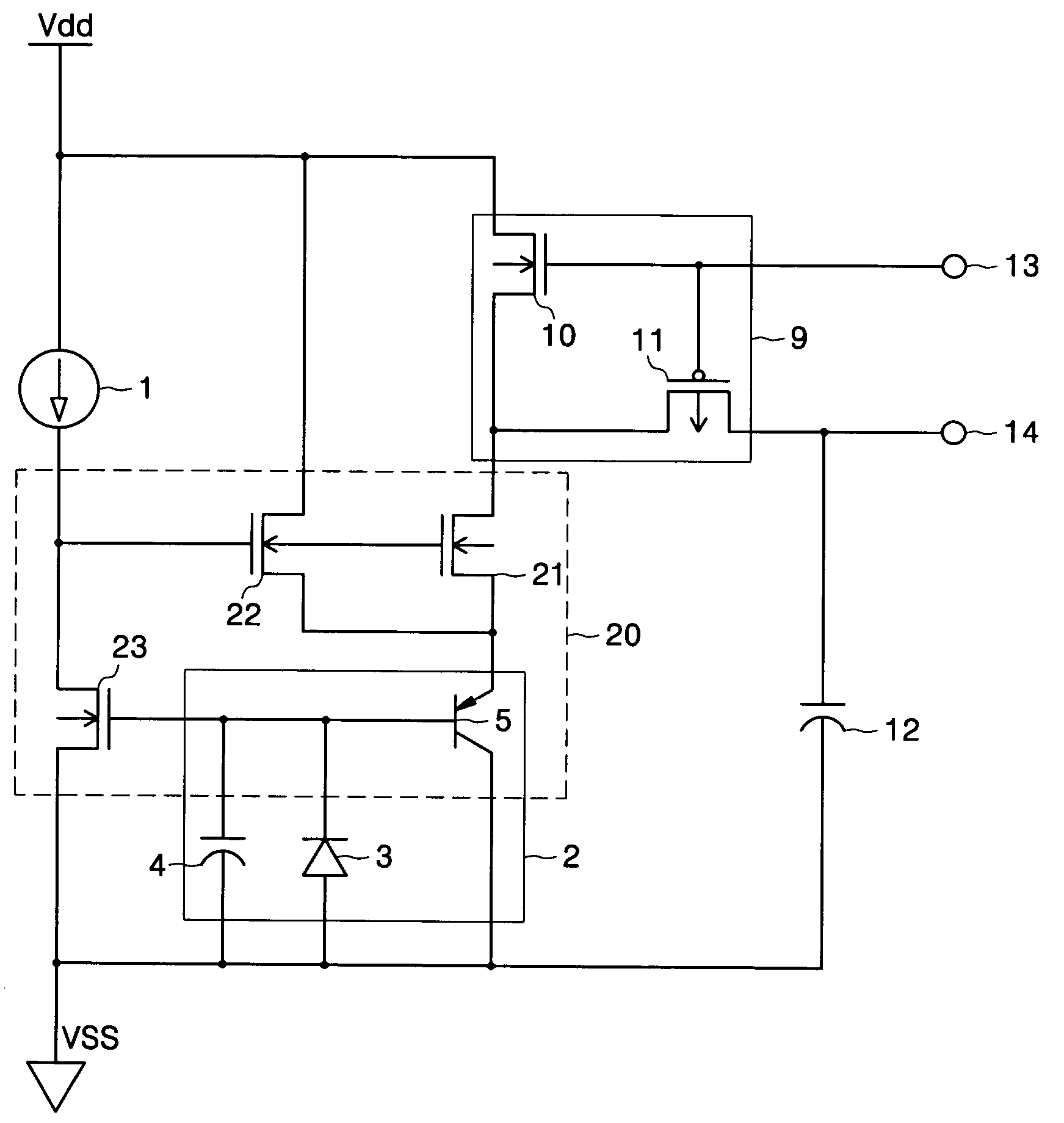
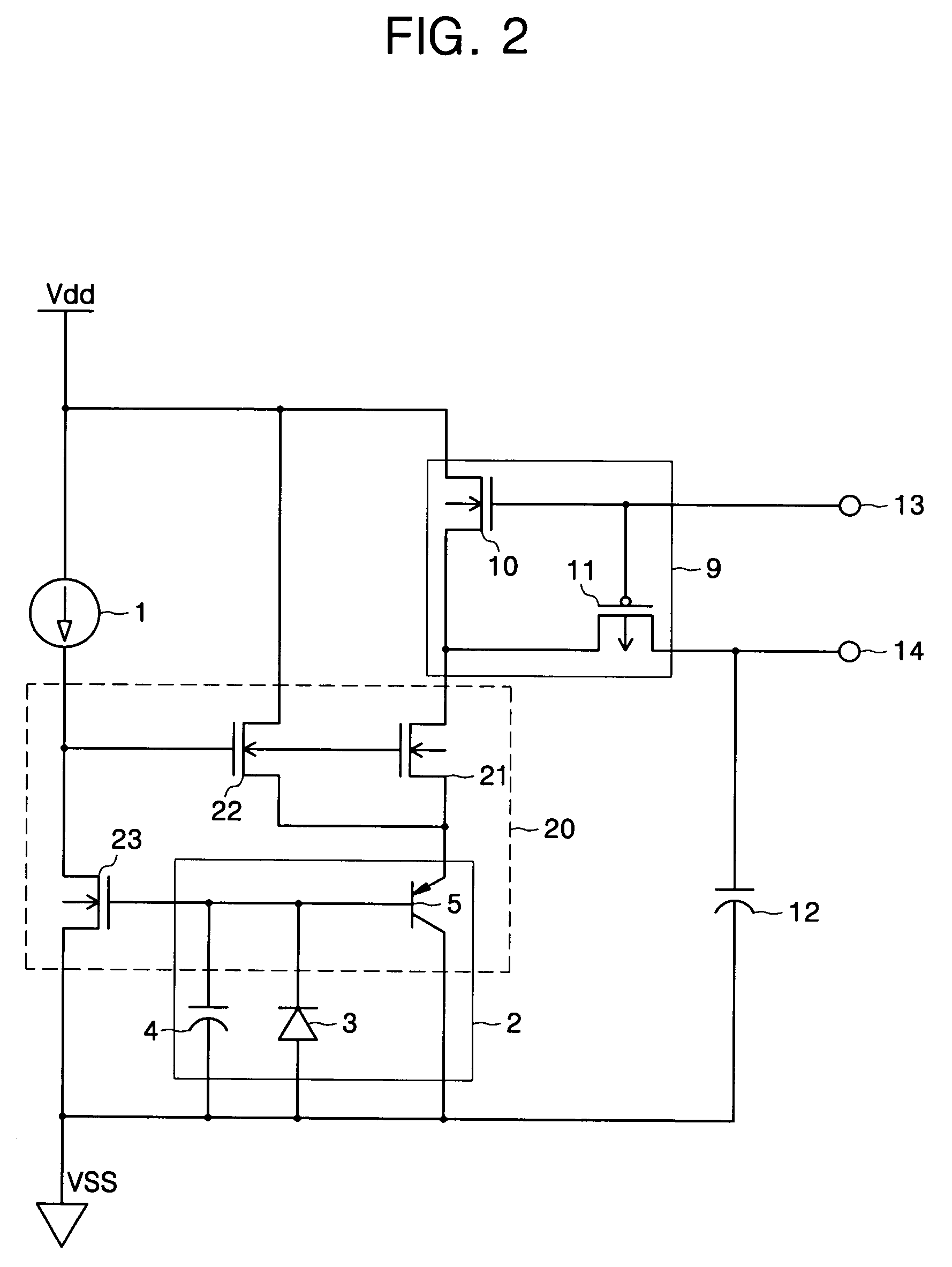
[0034]FIG. 2 is a diagram showing a photocurrent sensing circuit having a stabilized feedback loop according to the present invention.
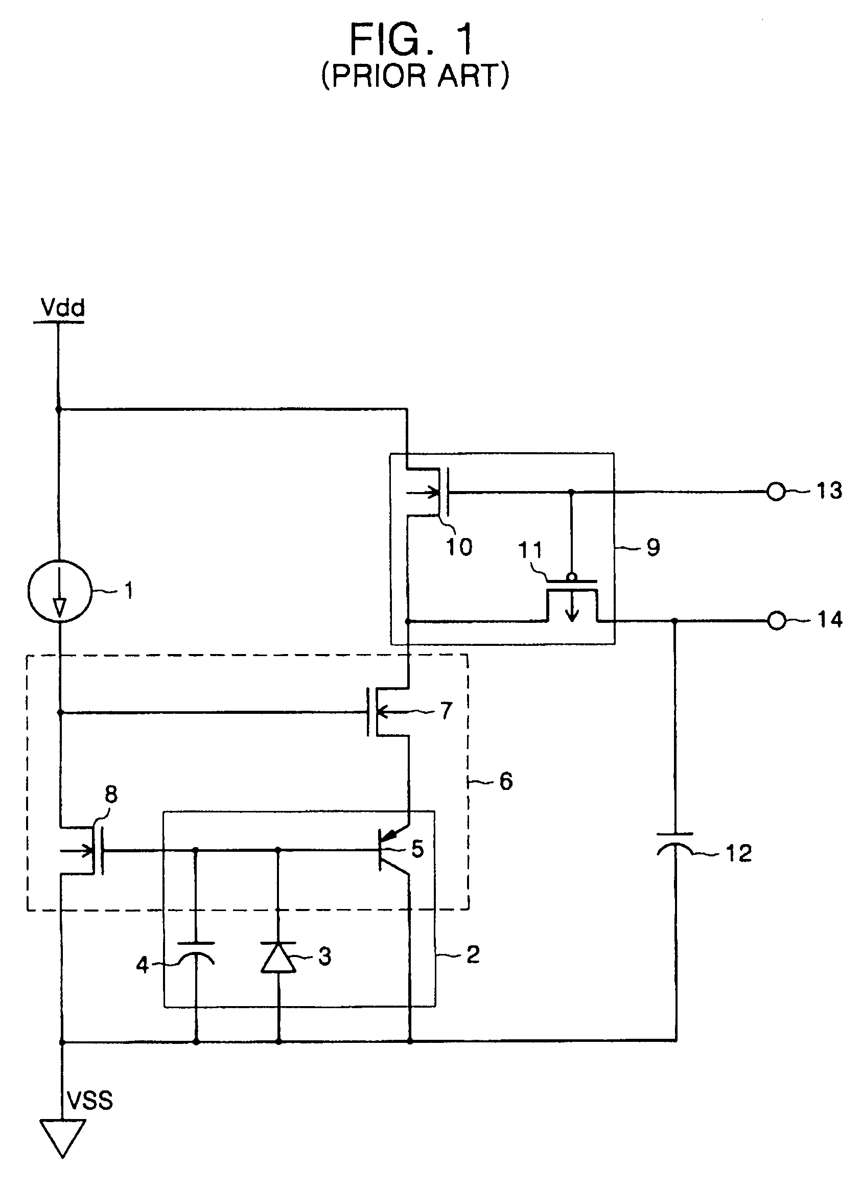
[0035]The photocurrent sensing circuit of FIG. 2 ensures continuous stability of a feedback loop by adding an NMOS transistor 22 to the feedback loop 6 of the photocurrent sensing circuit of FIG. 1. Therefore, like numbers refer to like elements for a circuit that has the same configuration and operation as in FIG. 1 so that the detailed description thereof will be omitted.
[0036]Still referring to FIG. 2, a feedback loop 20 of the photocurrent sensing circuit of the present invention further includes an NMOS transistor 22 where a drain node is connected to a power voltage, a gate node is connected to a current source 1, and a source node is connected to a PNP transistor 5. In the feedback loop 20, if both an NMOS transistor 10 and a PMOS transistor 11 turn off at the same time during a period that an output control signal transmitted from an output co...
second embodiment
[0039]FIG. 3 is a diagram showing a photocurrent sensing circuit having a stabilized feedback loop according to the present invention.
[0040]The photocurrent sensing circuit of FIG. 3 is an example of a circuit that has a wider operating voltage range and improved uniformity of the photocurrent sensing circuit together with the stabilized feedback loop 20 of FIG. 2.
[0041]Like numbers refer to like elements for a circuit that has the same configuration and operation as in FIG. 2 so that the detailed description thereof will be omitted.
[0042]Still referring to FIG. 3, a photocurrent generating unit 30 of the photocurrent sensing circuit of the present invention includes a photodiode 31 that generates a photocurrent in response to the amount of light incident into an optical sensor; and a parasitic capacitor 32 of the photodiode.
[0043]Here, the photocurrent generated in the photodiode 31 is directly delivered to an NMOS transistor 21, and the photocurrent delivered through the NMOS tran...
third embodiment
[0046]FIG. 4 is a diagram showing a photocurrent sensing circuit having a stabilized feedback loop according to the present invention.
[0047]The photocurrent sensing circuit of FIG. 4 is an example of a circuit that has a simpler configuration of the photocurrent sensing circuit together with the stabilized feedback loop 20 of FIG. 2.
[0048]Like numbers refer to like elements for a circuit that has the same configuration and operation as in FIG. 2 so that the detailed description thereof will be omitted.
[0049]Still referring to FIG. 4, a switching unit 44 of the photocurrent sensing circuit of the present invention includes a PMOS transistor 45 that turns on when an output control signal of the switching unit 44 is Shutter On, and turns off when the output control signal is Shutter Off.
[0050]Therefore, a feedback loop 40 is continuously maintained irrespective of operation of the switching unit 44 of the photocurrent sensing circuit, to keep constant a base voltage of a PNP transistor...
PUM
 Abstract
Description
Claims
Application Information
 - R&D
- Intellectual Property
- Life Sciences
- Materials
- Tech Scout
- Unparalleled Data Quality
- Higher Quality Content
- 60% Fewer Hallucinations
Browse by: Latest US Patents, China's latest patents, Technical Efficacy Thesaurus, Application Domain, Technology Topic, Popular Technical Reports.
© 2025 PatSnap. All rights reserved.Legal|Privacy policy|Modern Slavery Act Transparency Statement|Sitemap|About US| Contact US: help@patsnap.com


