Control apparatus for a vehicular 4-wheel drive system

a technology for controlling apparatus and vehicular 4-wheel drive, which is applied in the direction of control devices, vehicle components, transportation and packaging, etc., can solve the problems of deterioration of fuel economy of the vehicular 4-wheel drive system, reduce the deterioration of fuel economy, and reduce the noise generated

Active Publication Date: 2016-09-13
TOYOTA JIDOSHA KK
View PDF4 Cites 7 Cited by
  • Summary
  • Abstract
  • Description
  • Claims
  • Application Information

AI Technical Summary

Benefits of technology

[0007]The present invention was made in view of the background art described above. It is therefore an object of the present invention to provide a control apparatus for a vehicular 4-wheel drive system provided with primary drive wheels to which a drive force is transmitted from a drive power source, auxiliary drive wheels to which the drive force is selectively transmitted, a first clutch configured to selectively place a first power transmitting path between the drive power source and the auxiliary drive wheels, in a power transmitting state and a power cutoff state, and a second clutch disposed in a second power transmitting path between the first clutch and the auxiliary drive wheels, to selectively place the second power transmitting path in a power transmitting state and a power cutoff state, the control apparatus permits reduction of a noise generated in a 2-wheel drive mode of the vehicular 4-wheel drive system, while reducing deterioration of fuel economy of the vehicular 4-wheel drive system.
[0009]In the control apparatus according to the present invention described above, the first clutch is brought into the partially engaged or slipping state when the predetermined condition in which the vehicular 4-wheel drive system generates or is considered to generate the noise is satisfied in the 2-wheel drive mode in which the first and second clutches are placed in the fully released states. Accordingly, rotary members disposed between the first and second clutches are prevented from being rotated as established in a 4-wheel drive mode of the vehicular 4-wheel drive system, and backlashes existing in a spline-coupling portion and any other portion of a drive line of the vehicular 4-wheel drive system are eliminated. Thus, the present control apparatus permits reduction of the noise generated in the 2-wheel drive mode, while reducing deterioration of the fuel economy of the vehicular 4-wheel drive system.
[0010]In one preferred form of the invention, the first-clutch control portion places the first clutch in the partially engaged state while the second clutch is held in the fully released state. In this form of the invention, rotary motions of the auxiliary drive wheels are prevented from being transmitted toward the first clutch through the second clutch in the 2-wheel drive mode in which the second clutch is held in the fully released state while the first clutch is placed in the partially engaged state.
[0011]In another preferred form of the invention, the first-clutch control portion controls the partially engaged state of the first clutch on the basis of rotating speed of two rotary members disposed on respective opposite sides of the first clutch so as to prevent from a fully engaged state of the first clutch. In this form of the invention, the rotary member disposed between the first and second clutches is prevented from being rotated at a high speed as established in the fully engaged state of the first clutch, so that the deterioration of the fuel economy can be reduced.
[0012]In a further preferred form of the invention, the above-described predetermined condition is satisfied when at least one of the following conditions is satisfied: an operating speed of the drive power source falls within a predetermined range; a load of the drive power source is equal to or larger than a predetermined value; a transmission operatively connected to the drive power source is presently placed in any one of at least one predetermined high-gear shift position; and a lock-up clutch provided in a torque converter disposed between the drive power source and the transmission is placed in a fully engaged state or a partially engaged state. In this form of the invention, the first clutch is placed in the partially engaged state when the drive power source has a large amount of torque variation during its operation at a relatively low speed or under a relatively high load, or when the torque variation of the drive power source is likely to be transmitted through the drive line while the lock-up clutch is placed in the fully or partially engaged state, so that the generation of the noise due to the torque variation of the drive power source can be effectively reduced. Namely, the first clutch is not unnecessarily placed in the partially engaged state when the drive power source does not have a large amount of torque variation, so that the deterioration of the fuel economy of the vehicular 4-wheel drive system can be effectively reduced.

Problems solved by technology

Accordingly, the rotary members disposed between the first and second clutches are rotated at the same speeds as in the engaged state of the first clutch, resulting in deterioration of fuel economy of the vehicular 4-wheel drive system due to the rotary motions of those rotary members.

Method used


Image

  • Control apparatus for a vehicular 4-wheel drive system
  • Control apparatus for a vehicular 4-wheel drive system
  • Control apparatus for a vehicular 4-wheel drive system

Examples


first embodiment

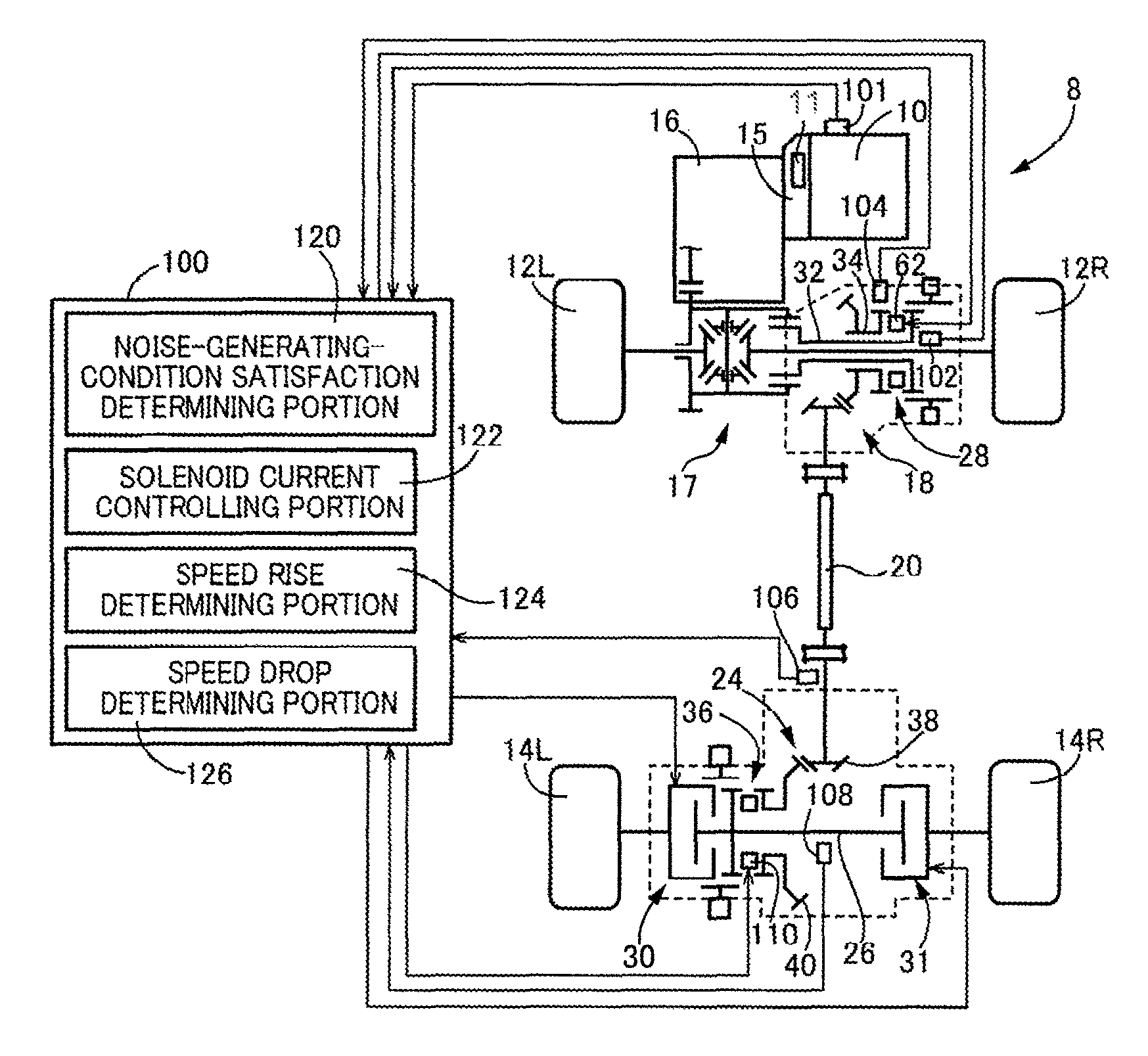
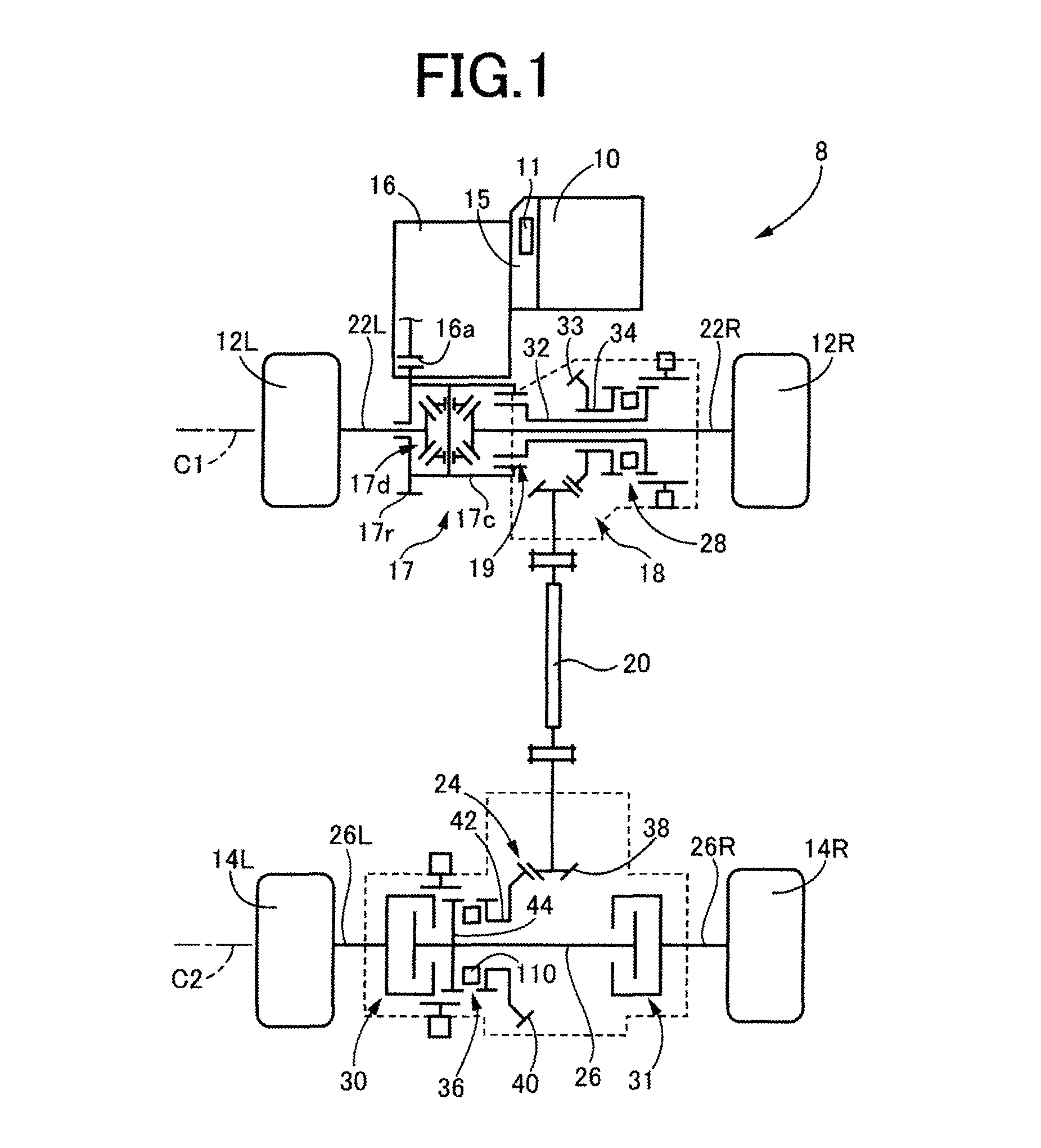
[0022]Referring first to the schematic view of FIG. 1, there is shown an arrangement of one example of a vehicular 4-wheel drive system 8 (hereinafter referred to simply as “4-wheel drive system 8”) to which a control apparatus according to the present invention is applicable. The 4-wheel drive system 8 is configured to drive a vehicle which is an FF type (front-engine front-drive type) vehicle in a 2-wheel drive mode. As shown in FIG. 1, the 4-wheel drive system 8 includes: a drive power source in the form of an engine 10; a first power transmitting path through which a drive force of the engine 10 is transmitted to left and right front wheels 12L and 12R (hereinafter collectively referred to as “front wheels 12”, unless otherwise specified); a second power transmitting path through which the drive force of the engine 10 is selectively transmitted to left and right rear wheels 14L and 14R (hereinafter collectively referred to as “rear wheels 14”, unless otherwise specified). The fr...

second embodiment

[0079]FIG. 7 is the schematic view showing an arrangement of another example of a vehicular 4-wheel drive system to which the control apparatus according to the invention is applicable. As shown in FIG. 7, the present vehicular 4-wheel drive system 150 (hereinafter referred to simply as “4-wheel drive system 150”) includes: a drive power source in the form of an engine 149; left and right front wheels 151L and 151R (hereinafter collectively referred to as “front wheels 151”, unless otherwise specified); left and right rear wheels 153L and 153R (hereinafter collectively referred to as “rear wheels 153”, unless otherwise specified); and a power transmitting device 152 which transmits a drive force of the engine149 to the front wheels 151 and the rear wheels 153. The rear wheels 153 are primary drive wheels driven by the drive force in both of a 2-wheel drive mode and a 4-wheel drive mode of the 4-wheel drive system 150, while the front wheels 151 are auxiliary drive wheels not driven ...


PUM


Abstract

A control apparatus for a vehicular 4-wheel drive system provided with: primary drive wheels to which a drive force is transmitted from a drive power source; auxiliary drive wheels to which the drive force is selectively transmitted; a first clutch configured to selectively place a first power transmitting path in a power transmitting state and a power cutoff state; and a second clutch disposed in a second power transmitting path to selectively place the second power transmitting path in a power transmitting state and a power cutoff state. The first and second clutches are placed in fully released states to establish a 2-wheel drive mode. The control apparatus includes a first-clutch control portion configured to bring the first clutch into a partially engaged state when a predetermined condition in which the vehicular 4-wheel drive system generates or is considered to generate a noise is satisfied in the 2-wheel drive mode.

Description

CROSS REFERENCE TO RELATED APPLICATION[0001]The present application claims the priority from Japanese Patent Application No. 2014-212120 filed on Oct. 16, 2014, the disclosure of which is herein incorporated by reference in its entirety.BACKGROUND OF THE INVENTION[0002]1. Field of the Invention[0003]The present invention relates generally to a control apparatus for a vehicular 4-wheel drive system, and more particularly to a control of a 4-wheel drive system of a vehicle provided with primary drive wheels and auxiliary drive wheels.[0004]2. Description of Related Art[0005]There is known a vehicular 4-wheel drive system provided with: primary drive wheels to which a drive force is transmitted from a drive power source; auxiliary drive wheels to which the drive force is selectively transmitted; a transfer device configured to distribute a torque from the drive power source to the primary drive wheels and the auxiliary drive wheels; and a coupling device configured to adjust the drive ...

Claims


Application Information

Patent Timeline
Patent Type & Authority Patents(United States)
IPC IPC(8): B60K23/08B60K17/354B60K17/02
CPCB60K23/08B60K17/02B60K17/354B60K17/344B60K17/35B60K17/3515B60K23/0808B60K2023/085
Inventor MAEDA, YOSHINORIYOSHIMURA, TAKAHIROHORIE, RYOTATAMURA, HIROSHITAMOTO, HIDEKI
Owner TOYOTA JIDOSHA KK
Why Eureka
Try Eureka