Landing hazard avoidance display

a display and hazard technology, applied in the field of navigation, aviation, avionics, can solve the problems of not providing the necessary depth cues for pilots, not being able to measure the surface profile more accurately than other technologies, and much of the terrain on the far side of the balloon to be unsafe for landing, etc., to achieve small safe spots or safe spots. , the effect of fine resolution

Active Publication Date: 2016-09-20
RAPID IMAGING TECH LLC +1
View PDF6 Cites 2 Cited by
  • Summary
  • Abstract
  • Description
  • Claims
  • Application Information

AI Technical Summary

Benefits of technology

[0014]The hazard map can be a simple display having little more than, for example, red areas, green areas, and an indicator of the vehicles position. The hazard map can be a colorization of a surface map such that the user can see ground detail. For example, a surface map can be a grey scale rendering of the surface topology or surface features. Unsafe areas can use different shades of red instead of grey whereas safe areas can use shades of green. Other colorizations include tinting and colored partially transparent overlays.
[0016]Of further note, the hazard display can have sufficiently fine resolution that very small safe spots or unsafe can be indicated. For example, a vehicle with landing pads can land wherever its pads touch green (safe), even if much of the terrain is red (unsafe). Similarly, that same craft can be rotated or shifted slightly to avoid putting a pad in a red spot.

Problems solved by technology

Traditional displays like synthetic vision systems do not provide the necessary depth cues to allow pilots to assess risk from obstacles quickly and accurately.
Regular imaging such as video can be used, but is less capable of measuring the surface profile than other technologies.
For example, the ground slope is a good criterion because it is usually unsafe to attempt landing on the edge of a cliff or steep mountainside.
For example, a hot air balloon floating past can cause much of the terrain on the far side of the balloon to be unsafe for landing.
As the balloon moves, some terrain becomes safe and other terrain becomes unsafe.

Method used


Image

  • Landing hazard avoidance display
  • Landing hazard avoidance display
  • Landing hazard avoidance display

Examples


Embodiment Construction

[0023]The particular values and configurations discussed in these non-limiting examples can be varied and are cited merely to illustrate embodiments and are not intended to limit the scope of the invention.

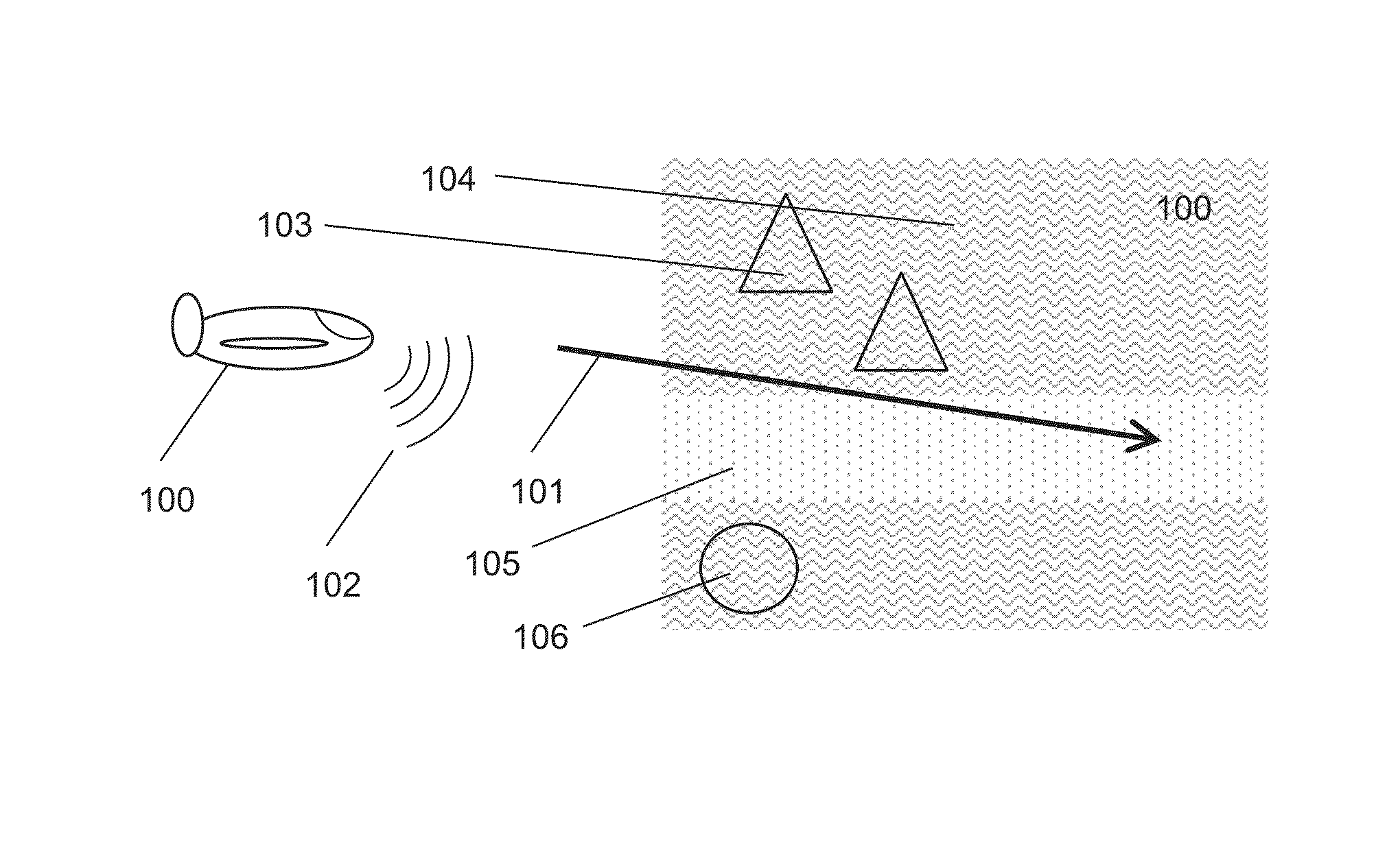
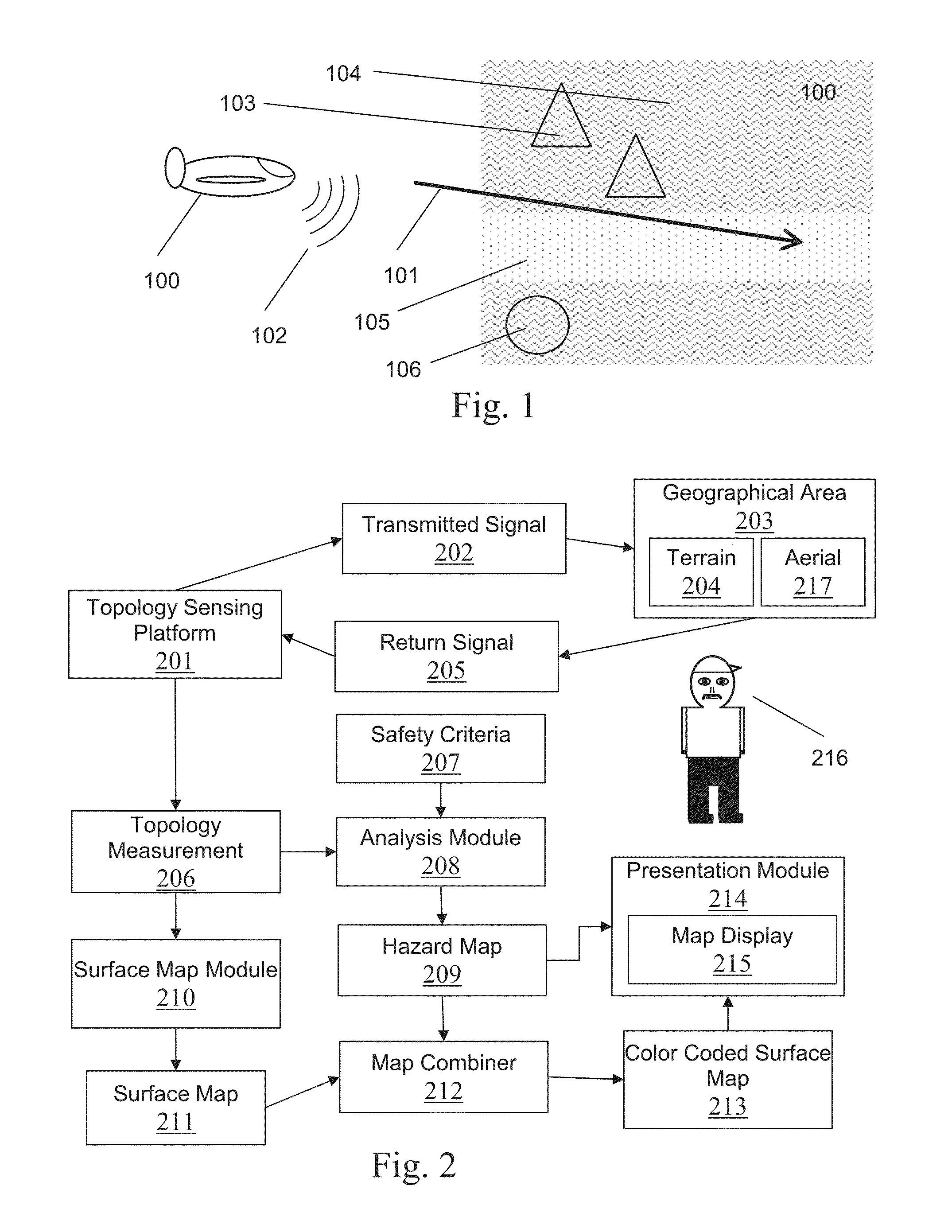
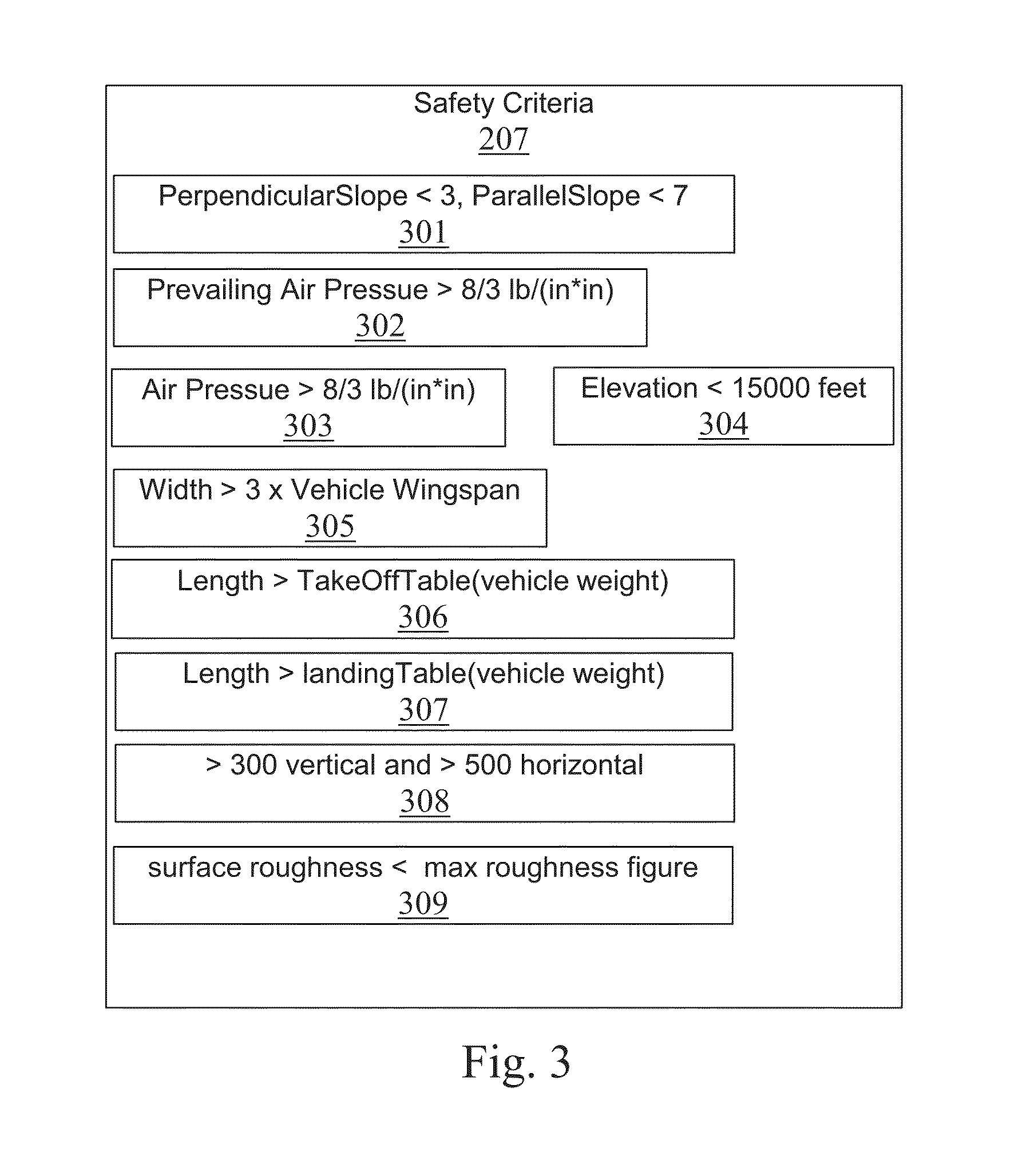
[0024]Landing hazard avoidance displays can provide rapidly understood visual indications of where it is safe to land a vehicle and where it is unsafe to land a vehicle. Color coded maps can indicate zones in two dimensions relative to the vehicles position where it is safe to land. The map can be simply green (safe) and red (unsafe) areas with an indication of scale or can be a color coding of another map such as a surface map. The color coding can be determined in real time based on topological measurements and safety criteria to thereby adapt to dynamic, unknown, or partially known environments.

[0025]FIG. 1 illustrates a vehicle 10 sensing the geographic topography along its flight path 101 and producing a two dimensional hazard map 100 in accordance with aspects of the embodim...


PUM


Abstract

Landing hazard avoidance displays can provide rapidly understood visual indications of where it is safe to land a vehicle and where it is unsafe to land a vehicle. Color coded maps can indicate zones in two dimensions relative to the vehicles position where it is safe to land. The map can be simply green (safe) and red (unsafe) areas with an indication of scale or can be a color coding of another map such as a surface map. The color coding can be determined in real time based on topological measurements and safety criteria to thereby adapt to dynamic, unknown, or partially known environments.

Description

STATEMENT OF GOVERNMENT INTEREST[0001]This invention described herein was made in part by an employee of the United States Government and was made with government support under contract numbers NNX09CB10C and NNX08CC40P awarded by NASA. The invention described herein may be manufactured and used by or for the Government of the United States of America for governmental purposes without the payment of any royalties thereon or therefor.TECHNICAL FIELD OF THE INVENTION[0002]Embodiments relate to navigation, aviation, and avionics for landing aircraft, spacecraft, and submarines. In particular, embodiments relate to display of information to allow an impromptu selection of a hazard-free landing site.BACKGROUND[0003]Prior art landing hazard displays concentrate on showing a user the actual hazards present in landing zones. For example, tall buildings, antennae, and power lines can be indicated such that a pilot or remote operator can take notice and avoid the hazard. Such hazard displays ...

Claims


Application Information

Patent Timeline
Patent Type & Authority Patents(United States)
IPC IPC(8): B64D43/00
CPCB64D43/00G08G5/0021G08G5/0086G08G5/025G01C23/005
Inventor ABERNATHY, MICHAEL FRANKLINHIRSH, ROBERT L.
Owner RAPID IMAGING TECH LLC
Why Eureka
Try Eureka