
Cylinder head with cooling channel

a cooling channel and cylinder head technology, applied in the direction of engine cooling apparatus, mechanical apparatus, engine components, etc., can solve the problems of mechanical failure poor heat flow from the neck to the bulk poor cooling of the cylinder head, so as to reduce the build-up of heat in the cylinder head and restrict the power of the engine

Active Publication Date: 2016-09-20
MCLAREN AUTOMOTIVE
View PDF26 Cites 1 Cited by
  • Summary
  • Abstract
  • Description
  • Claims
  • Application Information

AI Technical Summary

Benefits of technology

[0005]One way of reducing the build-up of heat in the cylinder head is to restrict the power of the engine. However, this is not desirable in an engine intended for a sports vehicle.

Problems solved by technology

This typically results in inlet and exhaust ports occupying a large proportion of the area over each cylinder.
However, this causes another problem.
The thinness of these necks of material means that the flow of heat from the necks to the bulk of the cylinder head is relatively poor.
As a result, heat can build up in the necks.
That heat build-up could result in mechanical failure of the cylinder head.
The problem of heat build-up can be particularly acute in a neck between exhaust valves because of the high temperature of the exhaust gas.
However, this is not desirable in an engine intended for a sports vehicle.

Method used


Image

  • Cylinder head with cooling channel
  • Cylinder head with cooling channel
  • Cylinder head with cooling channel

Examples


Embodiment Construction

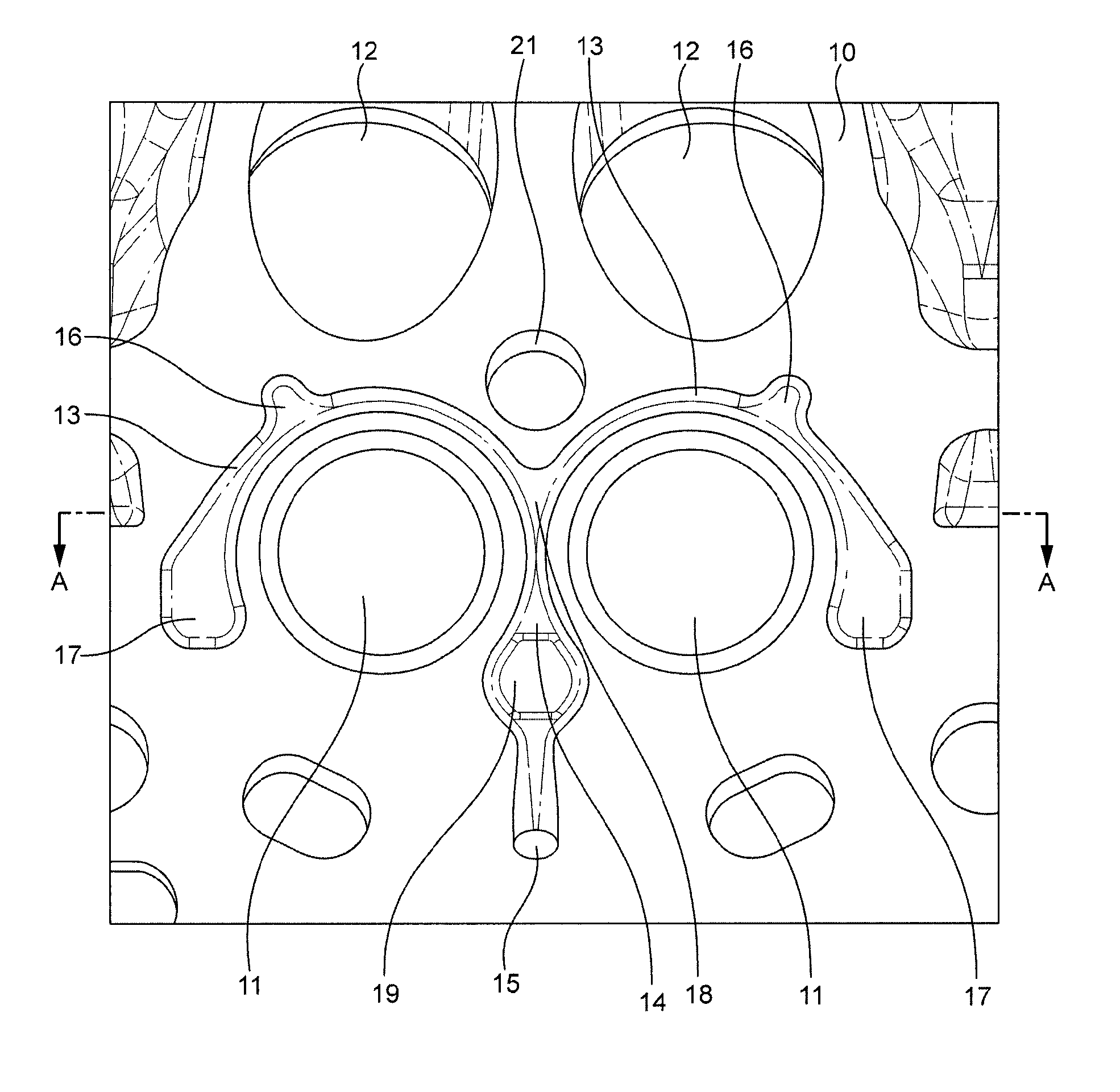
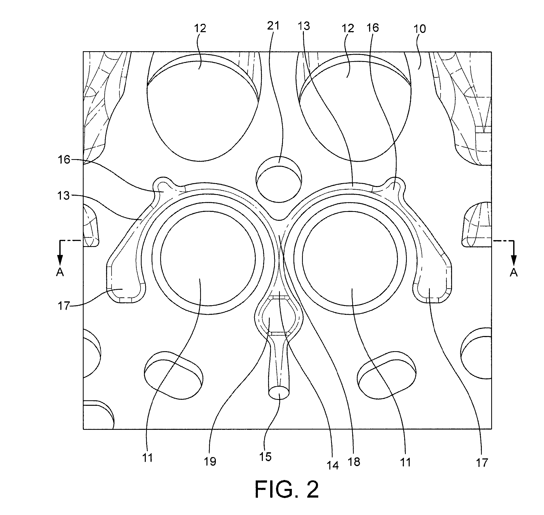
[0028]The cylinder head 10 of FIGS. 2 to 4 includes exhaust ports 11 and inlet ports 12. A coolant passageway 13, 14 is formed in the cylinder head. The passageway 13, 14 embraces the exhaust ports. In that way coolant flowing through the passageway can effectively extract heat from the region surrounding the exhaust ports.

[0029]In more detail, FIG. 2 shows a cross-section through part of a cylinder head perpendicular to the cylinder axis and facing the cylinders. The part of the cylinder head shown in FIG. 2 represents the majority of the part of the cylinder head that would face and cover a single cylinder. It comprises two inlet ports 12, two exhaust ports 11 and a hole 21 for receiving a spark plug as in some known cylinder heads. It also comprises arcuate channels indicated generally at 13 and 14 which embrace the exhaust ports. As will be described below, the arcuate channels are formed within the body of the cylinder head and when the cylinder head is built into an engine the...


PUM

PropertyMeasurementUnit
cross-sectional areaaaaaaaaaaa
cross-sectional areasaaaaaaaaaa
velocityaaaaaaaaaa

Abstract

A cylinder head for an internal combustion engine, the cylinder head including a region for covering a combustion cylinder, the region including one or more ports for communicating with the cylinder, and the cylinder head including a coolant channel that embraces at least one of the ports for cooling the zone of the cylinder head adjacent the port.

Description

CROSS-REFERENCE TO RELATED APPLICATIONS[0001]This patent application claims priority to Great Britain Patent Application GB 1303402.0, filed Feb. 26, 2013, entitled “Engine Cooling,” which is incorporated by reference.BACKGROUND[0002]This invention relates to engine cooling.BRIEF SUMMARY OF THE INVENTION[0003]A conventional internal combustion engine comprises an engine block which defines combustion cylinders. Each cylinder is closed at one end by a piston that is movable in the cylinder, and at the other end by a wall provided by a cylinder head. The cylinder head is a rigid unit that is attached firmly to the engine block. In order to permit combustion gas to enter the cylinders and exhaust gas to escape the cylinders are provided with valves which, when opened, permit the cylinders to communicate with inlet and exhaust channels. Conventionally the valves are mounted on the cylinder head and communicate with the cylinders through openings in the cylinder head.[0004]In designing a...

Claims


Application Information

Patent Timeline
Patent Type & Authority Patents(United States)
IPC IPC(8): F02F1/40F02F1/10F01P3/02
CPCF02F1/40F01P3/02F02F1/10Y10T29/4927F01P2003/024B22D15/02F01P3/14F02F1/36F02F1/38
Inventor ALEXANDER, STUART
Owner MCLAREN AUTOMOTIVE
Learn More