
Method for operating a direct fuel injection system

a fuel injection system and direct technology, applied in the direction of machines/engines, electric control, instruments, etc., can solve the problems of affecting the durability of the direct fuel injector, affecting the vaporization of fuel within the direct injector, depletion and not being available, etc., to reduce engine emissions, reduce pumping losses & fuel consumption, and improve fuel vaporization

Active Publication Date: 2016-09-27
FORD GLOBAL TECH LLC
View PDF9 Cites 3 Cited by
  • Summary
  • Abstract
  • Description
  • Claims
  • Application Information

AI Technical Summary

Benefits of technology

[0001]Engines may be configured with various fuel systems used to deliver a desired amount of fuel to an engine for combustion. One type of fuel system includes a port fuel injector and a direct fuel injector for each engine cylinder. The port fuel injectors may be operated to improve fuel vaporization and reduce engine emissions, as well as to reduce pumping losses & fuel consumption at low loads. The direct fuel injectors may be operated during higher load conditions to improve engine performance and fuel consumption at higher loads. Additionally, both port fuel injectors and direct injectors may be operated together under some conditions to leverage advantages of both types of fuel delivery.
[0004]In one example, some of the above described issues may be addressed with a method, comprising: during engine cylinder operation with fuel from a first injector and not a second injector: increasing a rail pressure of a fuel rail coupled to the second injector in response to a temperature increase of a tip of the second injector. In this way, an engine cylinder may be operated by combusting fuel from the first injector without affecting durability of the second injector. By raising the rail pressure of a fuel rail coupled to the second injector in response to a temperature increase of a tip of the second injector, the method may be utilized to prevent a vapor space from forming within the second injector, for example, within the tip of the second injector which is exposed to the heat of combustion within the engine cylinder. By preventing a vapor space from forming, the method may be used to prevent fuel distillation in the tip of the second injector during periods where the engine cylinder is operating with fuel from a first injector and not the second injector.
[0006]In yet another example, some of the above issues may be addressed by a method, comprising: operating an engine cylinder with fuel from a first injector and not a second injector; during a first condition, increasing a rail pressure of a fuel rail coupled to the second injector in response to a temperature increase of a tip of the second injector; and during a second condition, injecting fuel from the second injector into the engine cylinder in response to the temperature increase. In this way, liquid fuel may be injected by the second injector, thus cooling the injector in response to the temperature increase. Further, liquid fuel injection may be limited to specific operating conditions, thus maintaining or improving engine emissions and fuel economy during operation.

Problems solved by technology

Further, the increased temperature at the direct injector may lead to the vaporization of fuel within the direct injector.
This may lead to fuel distillation within the injector tip, which may lead to deposits internal to the injector, and in turn affect the durability of the direct fuel injector.
However, the inventors herein have recognized problems with this approach.
In another example, the direct fuel injectors may be coupled to a limited supply of fuel, which may thus be depleted and not be available when needed if fuel is constantly injected.
Further, the periodic injection of fuel through the direct injectors may not be sufficient to prevent vapor space formation within the portions of the injector exposed to the heat of combustion within the engine cylinders.
Further, liquid fuel injection may be limited to specific operating conditions, thus maintaining or improving engine emissions and fuel economy during operation.

Method used


Image

  • Method for operating a direct fuel injection system
  • Method for operating a direct fuel injection system
  • Method for operating a direct fuel injection system

Examples


Embodiment Construction

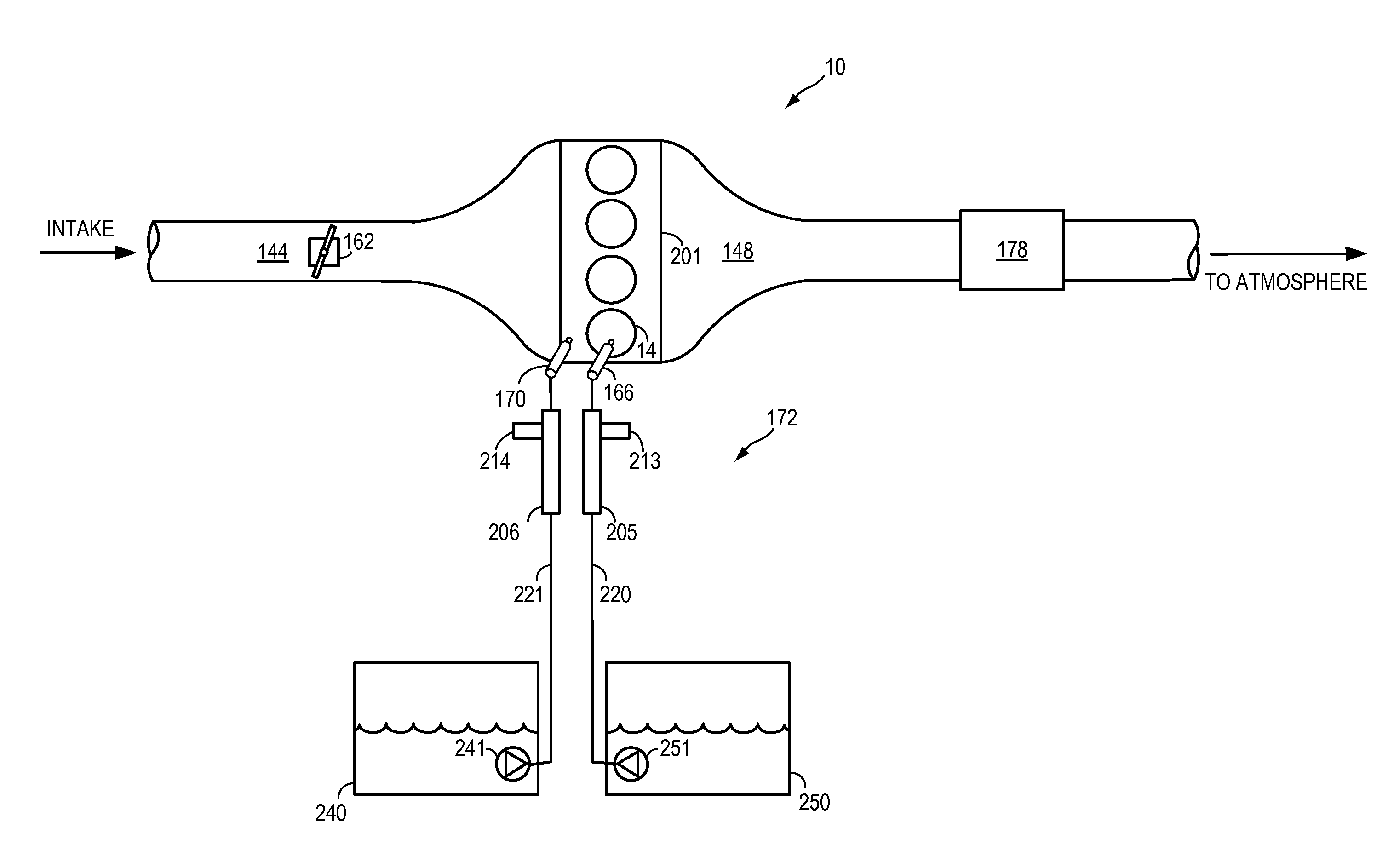
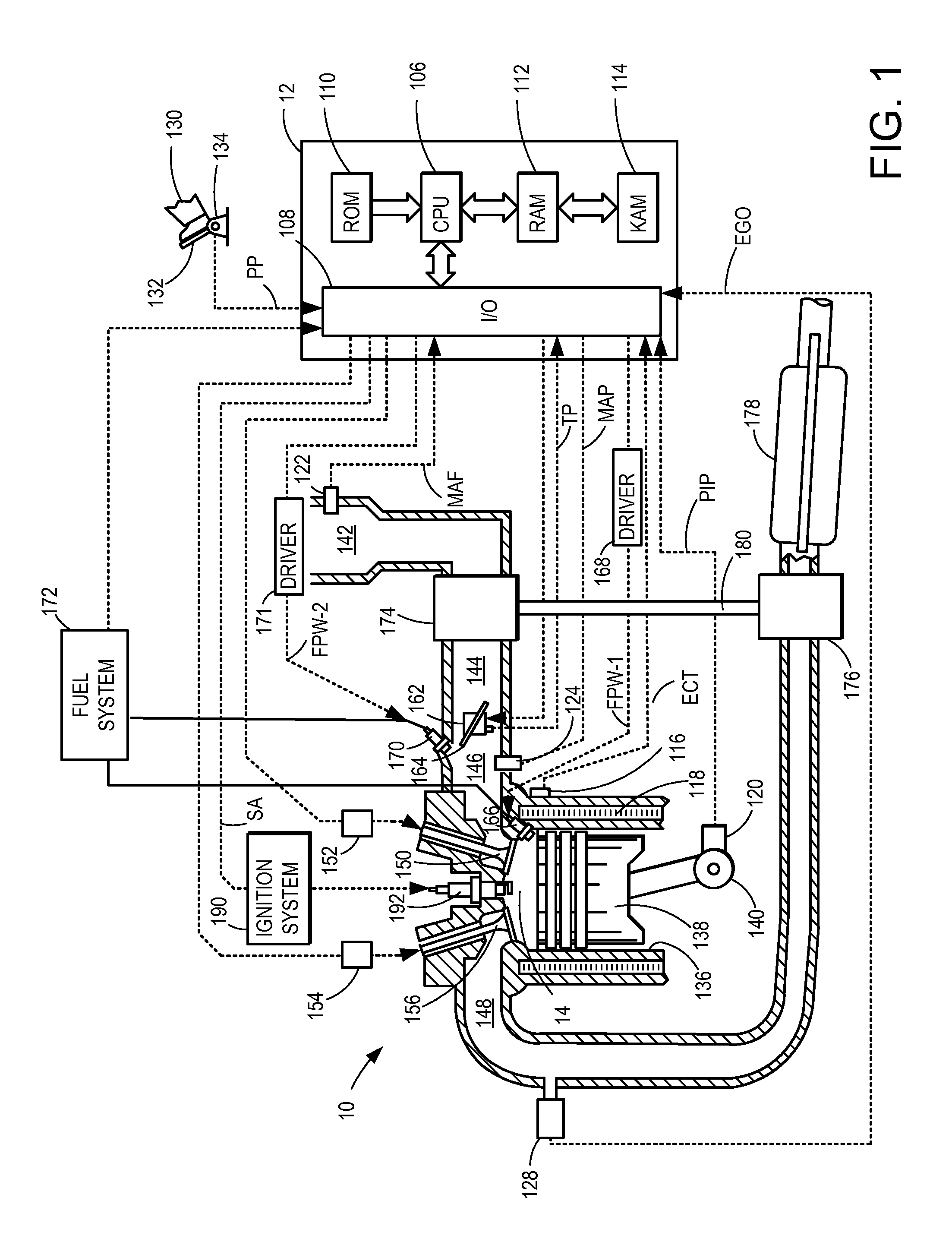
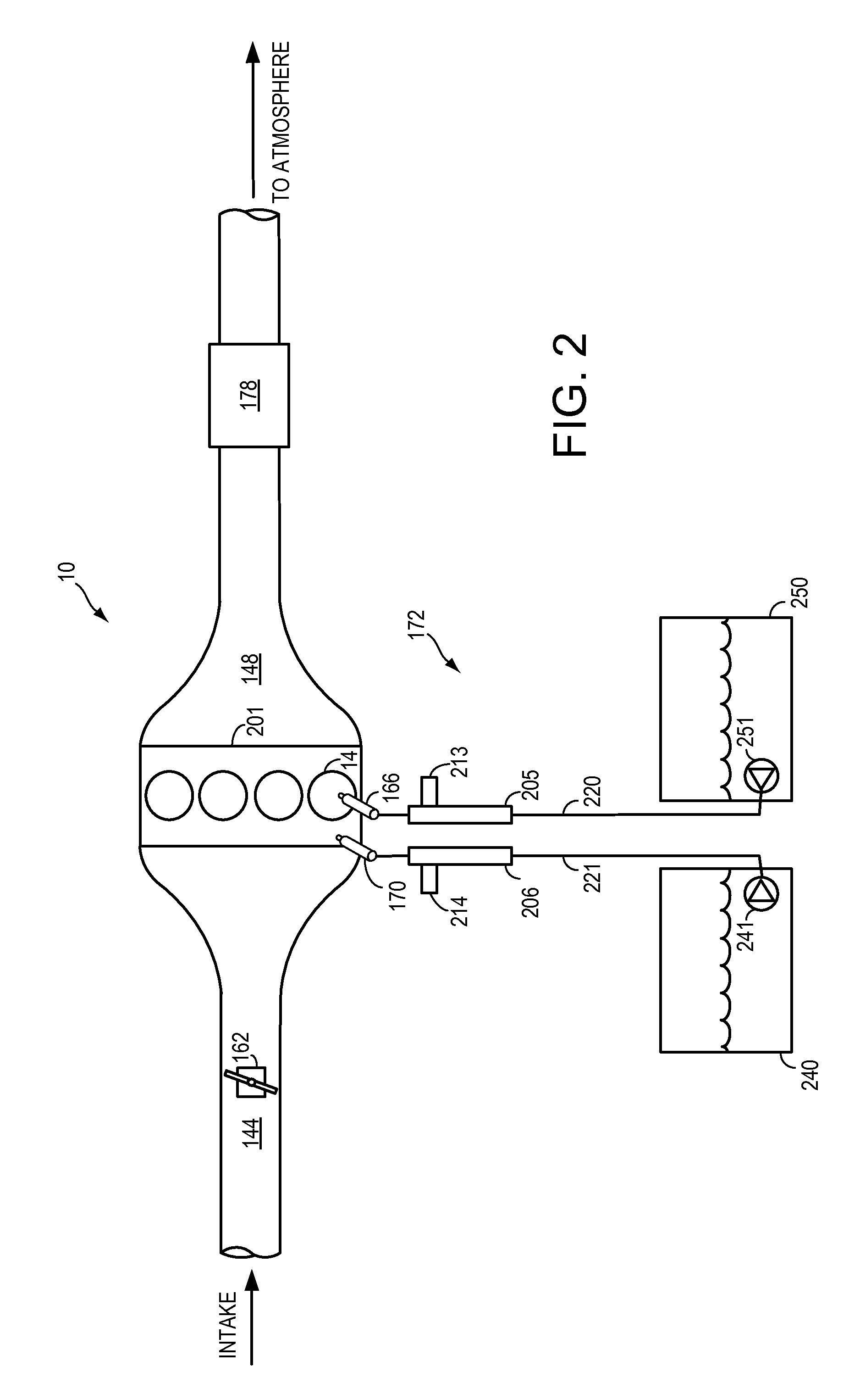
[0014]The present description relates to systems and methods for operating a direct fuel injection system within an engine system where more than one fuel injectors are coupled to an engine cylinder. In one non-limiting example, the engine may be configured as illustrated in FIG. 1. Further, additional components of a fuel injection system as depicted in FIG. 2 may be included in the engine depicted in FIG. 1. A method for operating a direct fuel injection may be provided by the systems illustrated in FIGS. 1 and 2 and the method illustrated in FIG. 3, which shows an example method for operating a direct fuel injector. An additional method for operating a direct fuel injection system is illustrated in FIG. 4. An example timeline for operating a direct fuel injection system in accordance with the above method and systems is depicted in FIG. 5.

[0015]FIG. 1 depicts an example embodiment of a combustion chamber or cylinder of internal combustion engine 10. Engine 10 may be controlled at...


PUM


Abstract

A method, comprising: during engine cylinder operation with fuel from a first injector and not a second injector: increasing a rail pressure of a fuel rail coupled to the second injector in response to a temperature increase of a tip of the second injector. In this way, by raising the rail pressure of a fuel rail coupled to the second injector in response to a temperature increase of a tip of the second injector, the method may be utilized to prevent a vapor space from forming within the tip of the second injector which is exposed to the heat of combustion within the engine cylinder. By preventing a vapor space from forming, the method may be used to prevent fuel distillation in the tip of the second injector during periods where the engine cylinder is operating with fuel from a first injector and not the second injector.

Description

BACKGROUND AND SUMMARY[0001]Engines may be configured with various fuel systems used to deliver a desired amount of fuel to an engine for combustion. One type of fuel system includes a port fuel injector and a direct fuel injector for each engine cylinder. The port fuel injectors may be operated to improve fuel vaporization and reduce engine emissions, as well as to reduce pumping losses & fuel consumption at low loads. The direct fuel injectors may be operated during higher load conditions to improve engine performance and fuel consumption at higher loads. Additionally, both port fuel injectors and direct injectors may be operated together under some conditions to leverage advantages of both types of fuel delivery.[0002]Engines operating with both port fuel injectors and direct injectors may operate for extended periods without using the direct injectors. During periods of non-use, the direct injector tips are exposed to high temperatures within the combustion cylinders resulting f...

Claims


Application Information

Patent Timeline
Patent Type & Authority Patents(United States)
IPC IPC(8): F02M37/00F02D41/30G01M15/00F02D41/38F02M59/46F02D41/00
CPCF02D41/3094F02D41/0025F02D41/3082F02D41/3845F02D41/0027F02D2041/389F02D2200/021F02D2200/0602F02D2200/0606F02D2250/02F02D2250/31F02M63/02
Inventor KRAMER, ULRICHCZEKALA, MICHAEL DAMIANPURSIFULL, ROSS DYKSTRA
Owner FORD GLOBAL TECH LLC
Learn More