Mounting rail for the interior construction of a switch cabinet housing

Active Publication Date: 2016-09-27
RITTALWERK RUDOLF LOH GMBH & CO KG
View PDF12 Cites 0 Cited by
  • Summary
  • Abstract
  • Description
  • Claims
  • Application Information

AI Technical Summary

Benefits of technology

[0013]It is preferred that the mounting rail comprises at least two slotted holes extending in longitudinal direction of the mounting rail which are arranged behind one another and spaced apart from another, wherein neighboring slotted holes ar

Problems solved by technology

The previously described mounting rail has the disadvantage that mounting thereof within the switch cabinet housing is comparably cumbersome.
The mounting rail has a further disadvantage that the clamping section t

Method used


Image

  • Mounting rail for the interior construction of a switch cabinet housing
  • Mounting rail for the interior construction of a switch cabinet housing
  • Mounting rail for the interior construction of a switch cabinet housing

Examples


Example

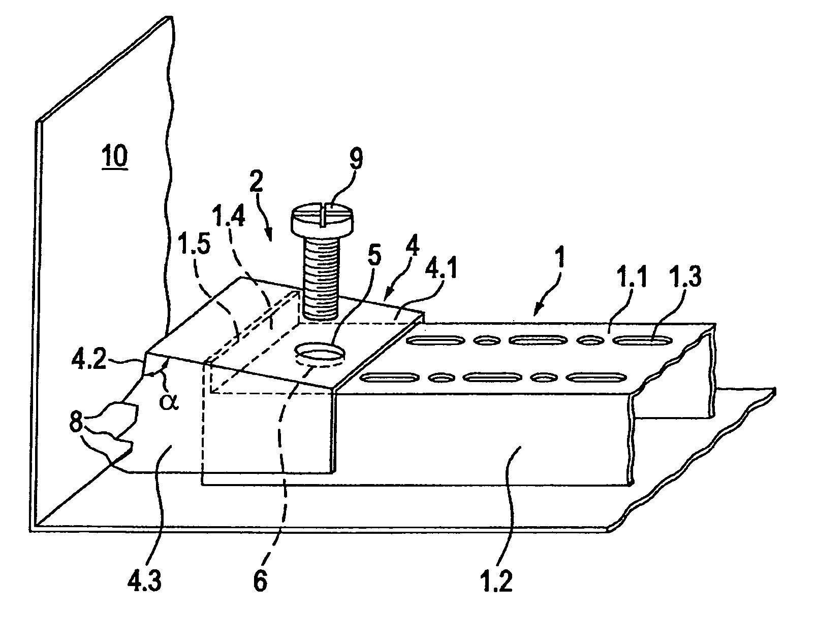
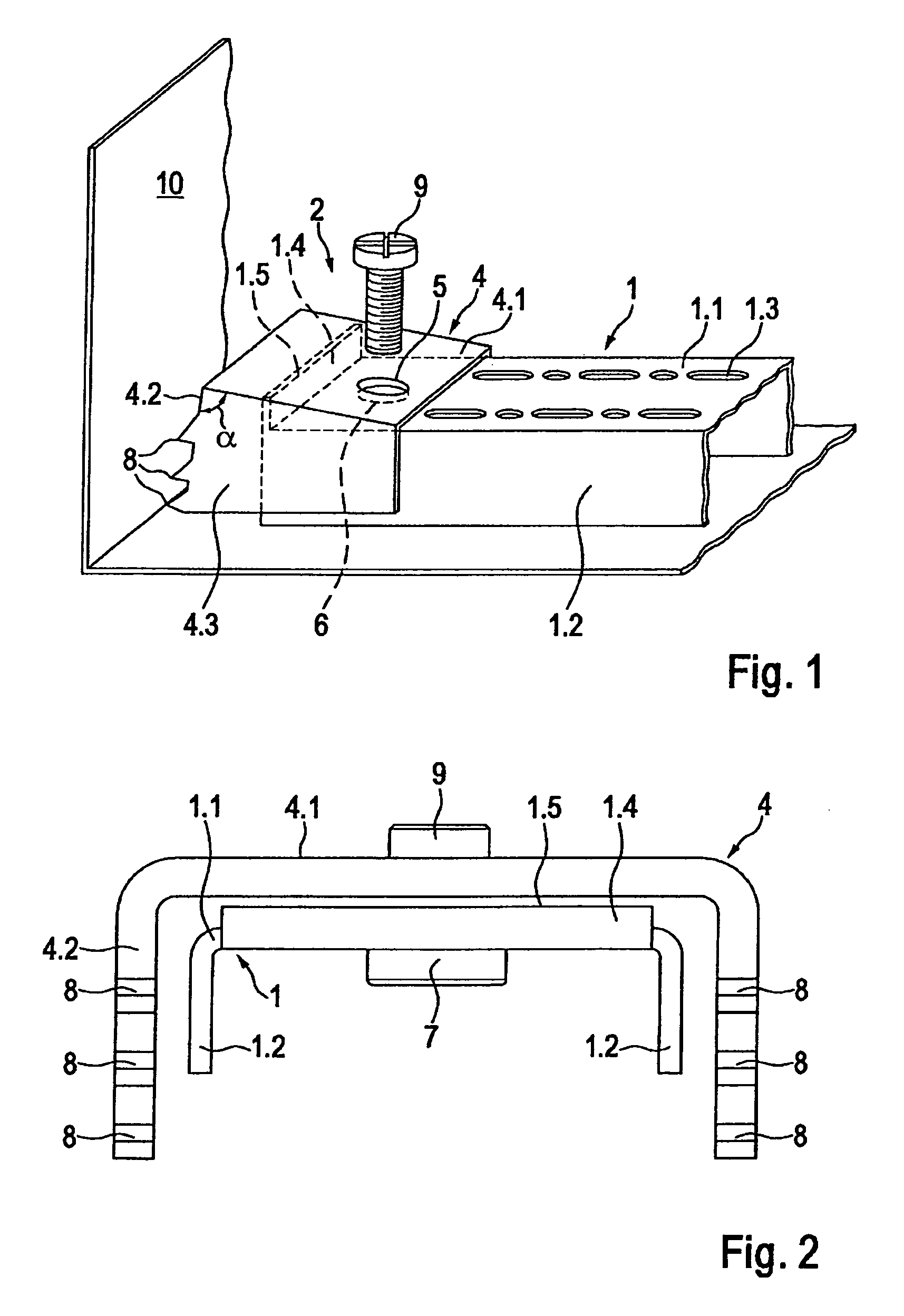
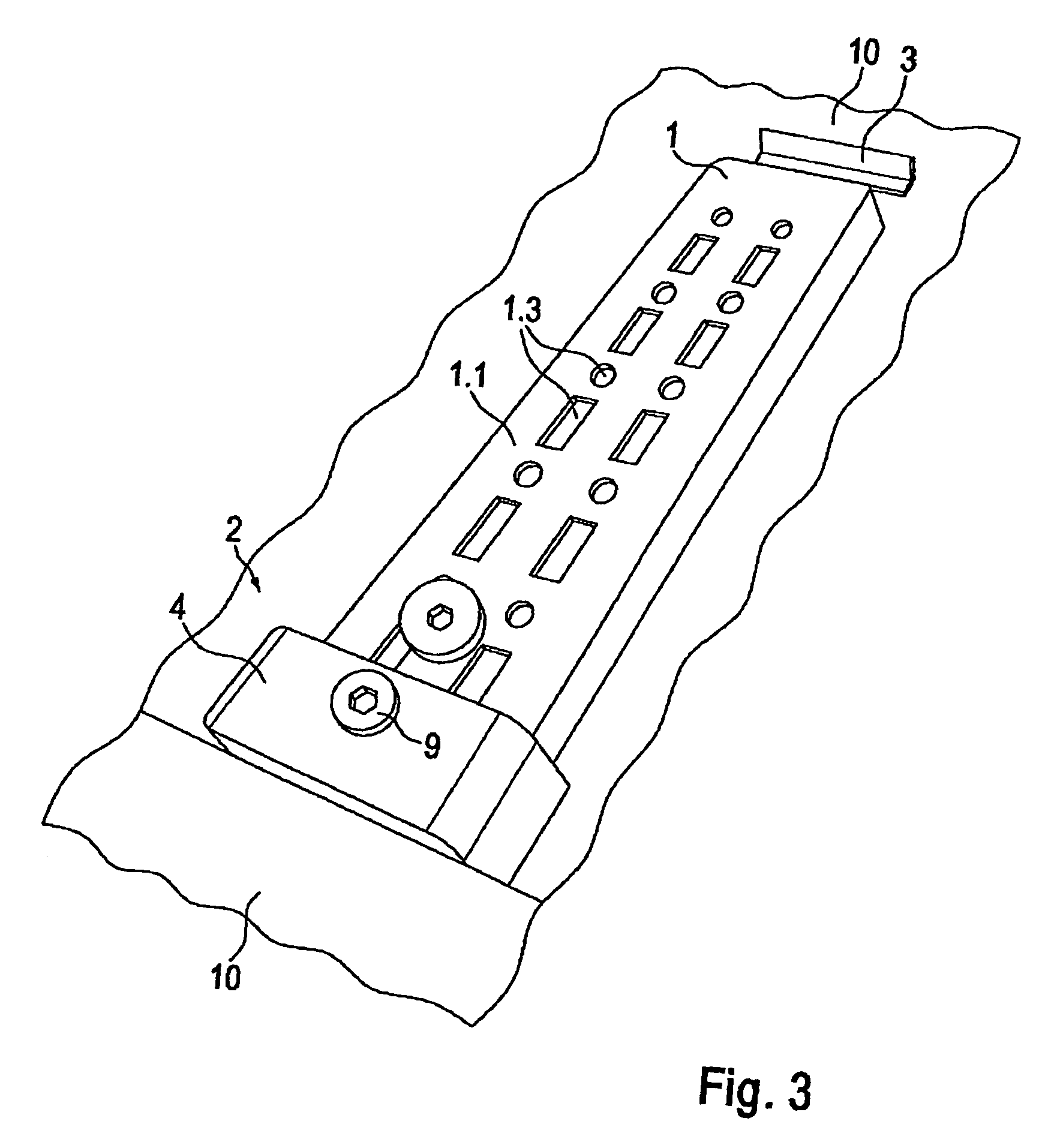
[0022]FIG. 1 illustrates a detailed view of a clamping section 2 of a first embodiment of the mounting rail for the interior construction of a switch cabinet housing according to the invention. Clamping section 2 directly adjoins the first end of mounting section 1 and includes a knee lever 4 having a fastening side 4.1 and a clamping side 4.2. Clamping side 4.2 and fastening side 4.1 include an angle α. Mounting section 1 is a U profile and comprises further to a mounting side 1.1 two parallel folded edges 1.2 bent from the mounting side 1.1 orthogonally which are spaced from another by mounting side 1.1. Mounting side 1.1 comprises a system perforation having attachment seats 1.3 which in the present case formed by two rows of alternately circular and rectangular cut-outs. Mounting side 1.1 comprises a bend 1.4 at its end facing towards clamping section 2, which bend in turn comprises a free end 1.5 extending parallel and spaced to the mounting side 1.1. Bend 1.4 is substantially ...


PUM


Abstract

The invention relates to a mounting rail for the interior construction of a switch cabinet housing, said mounting rail comprising a mounting section that has a clamping section at its first end and a support section at its second end opposite the first end, characterized in that the clamping section has a knee lever with a fastening side, via which the knee lever is detachably screwed to the first end of the mounting section and with a clamping side that includes an angle with the fastening side.

Description

BACKGROUND OF THE INVENTION[0001]The invention relates to a mounting rail for the interior construction of a switch cabinet housing, said mounting rail comprising a mounting section that has a clamping section at its first end and a support section at its second end opposite the first end.[0002]A mounting rail of this type is known from DE 10 2008 052 291 A1. Here, the support section is formed to be supported by the rear wall of the switch cabinet housing, while the clamping section can be clamped in the region of the front side of the switch cabinet housing with the aid of clamping means. For clamping, the clamping section comprises a leg oriented to the front side of the switch cabinet housing which is connected to the mounting section, and a deflection oriented at an angle to the leg, the deflection comprising at least one correcting element. At least in sections, the correcting element forms a clamping area. The deflection comprises a hole which is aligned with a threaded seat ...

Claims


Application Information

Patent Timeline
IPC IPC(8): A47B88/00H02B1/32
CPCH02B1/32
Inventor BENNER, ROLF
Owner RITTALWERK RUDOLF LOH GMBH & CO KG
Why Eureka
Try Eureka