Display device for improving crosstalk affecting three dimensional image quality and related method

a display device and image quality technology, applied in the field of display devices for showing three dimensional (3d) images and a display method, can solve the problems of users' less comfort and hard promotion of certain kinds of technology, and achieve the effect of improving 3d image crosstalk and enhancing 3d image quality

Active Publication Date: 2016-10-04
TCL CHINA STAR OPTOELECTRONICS TECH CO LTD
View PDF11 Cites 0 Cited by
  • Summary
  • Abstract
  • Description
  • Claims
  • Application Information

AI Technical Summary

Benefits of technology

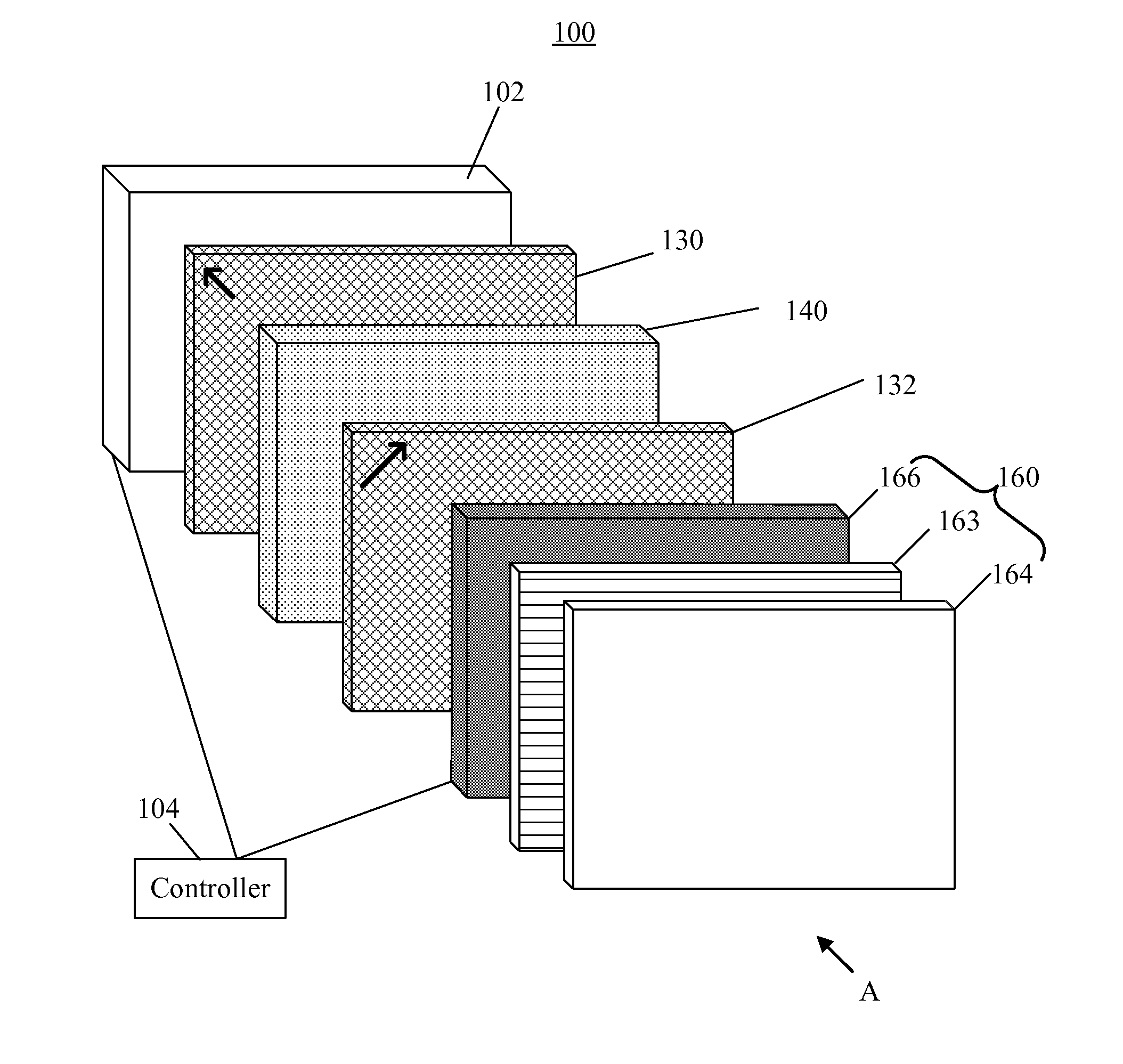
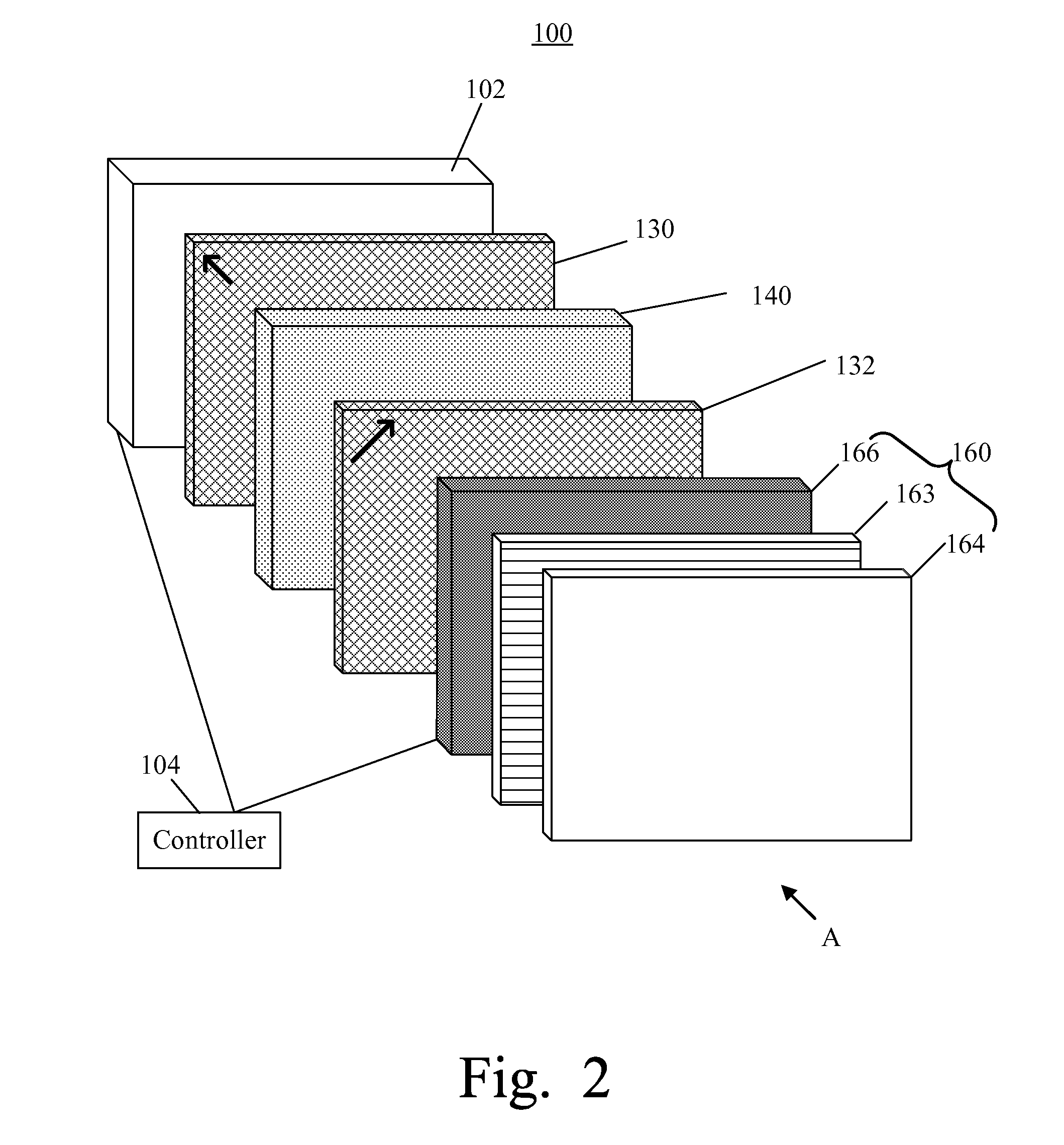
[0007]An object of the present invention is to propose a display device and a display method. The backlight module is divided into a plurality of light source units. The backlight module and the display panel are scanned simultaneously. After a display section of the display panel is scanned, the light source unit which the scanned display section corresponds to illuminates and the light source units which other wait-to-be-scanned display sections correspond to do not illuminate. This design helps improve 3D image crosstalk and enhance 3D image quality.
[0018]Compared with the conventional technology, the present invention provides a display device where the backlight module is divided into a plurality of light source units and where the backlight module and the display panel are scanned simultaneously. Whenever a display section of the display panel finishes being scanned, the light source unit which the scanned display section corresponds to illuminates and the light source units which other wait-to-be-scanned display sections correspond to do not illuminate. In this way, images in subsequent frames will not be viewed at the same time before all of the display sections of the display panel finish being scanned. It helps improve 3D image crosstalk and enhance 3D image quality.

Problems solved by technology

This kind of technology is a bit harder to promote widely since it requires the users to spend extra money to buy the specially-made glasses.
It also makes the users feel less comfortable since the users need to wear the specially-made glasses to view 3D images.

Method used


Image

  • Display device for improving crosstalk affecting three dimensional image quality and related method
  • Display device for improving crosstalk affecting three dimensional image quality and related method
  • Display device for improving crosstalk affecting three dimensional image quality and related method

Examples


first embodiment

[0031]Please refer to FIG. 4. FIG. 4 is a schematic diagram showing the display unit section 140, the grating sheet 160, and the backlight module 102 in operation according to the present invention. The display unit section 140 is scanned row by row along a direction as an arrow B shows until the final row finishes being scanned. The period of scanning time is called a frame rate. Afterwards, scanning continues again from the first row. In this embodiment of the present invention, the frame rate is set as 120 Hz for demonstration. In reality, the frame rate is not restricted. The backlight module 102 comprises the first light source unit 110 and the second light source unit 120. Preferably, the first light source unit 110 and the second light source unit 120 share half the illuminating area of the backlight module 102, respectively. The display unit section 140 comprises the first display section 141 and the second display section 142. Preferably, the first display section 141 and t...

third embodiment

[0042]Please refer to FIG. 8. FIG. 8 is a schematic diagram showing a display unit section 140, a grating sheet 160, and a backlight module 102 in operation according to the present invention. The display unit section 140 is scanned row by row along a direction as an arrow B shows until the final row finishes being scanned. The period of scanning time is called a frame rate. Afterwards, scanning continues again from the first row. The backlight module 102 comprises n light source units 110-1˜110-n where the n is a positive integer. Preferably, the illuminating range of each of the light source units is equal. The display unit section 140 comprises n display sections 141-1˜141-n. Preferably, each of the display sections comprises equal display units, and each of the display sections overlaps the illuminating range of one of the light source units.

[0043]Whenever a display section finishes being scanned, the light source which the display section corresponds to is turned on simultaneou...


PUM


Abstract

A display device for showing 3D images includes a backlight module and a display section. The backlight module includes n light source units. The display unit section includes n display sections. Upon conditions that a first through kth display section are scanned to receive an image in an current frame, a (k+1)th through an nth display section receives an image in a previous frame, a first through a kth light source unit generate light, and a (k+1)th through nth light source unit do not generate light, the first through the kth display sections display according to the image in the current frame and the light from the first through the kth light source unit, while the (k+1)th display section through the nth display section do not display the image in the previous frame due to the (k+1)th light source unit through the nth light source unit not generating light.

Description

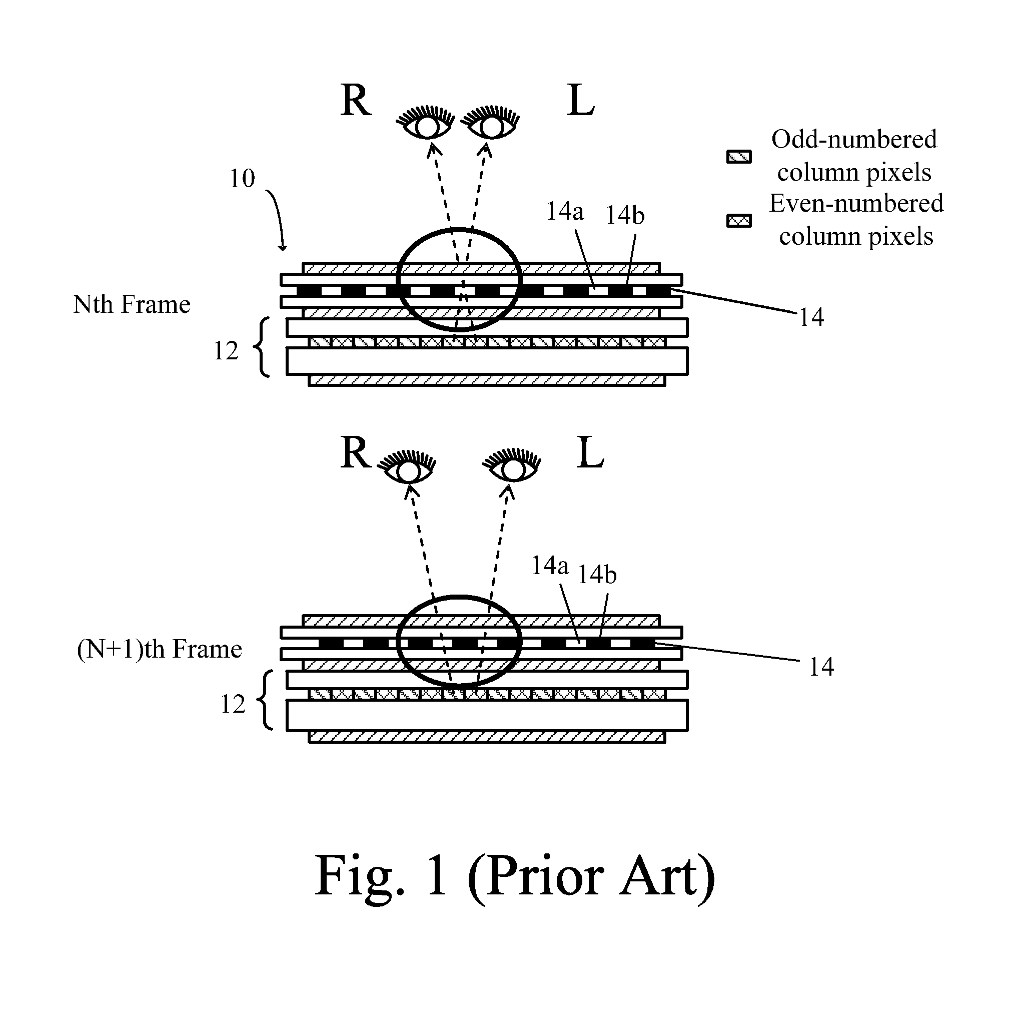
BACKGROUND OF THE INVENTION[0001]1. Field of the Invention[0002]The present invention relates to a display device for showing three dimensional (3D) images and a display method, and more particularly, to a display device for improving crosstalk affecting image quality and a display method adopting the device.[0003]2. Description of the Prior Art[0004]Human beings see real-world images using both eyes. Further, the human brain forms so-called 3D images (three-dimensional images) according to differences in spatial distance between two views seen by both eyes from two different angles. A so-called 3D display is designed to create simulations of human visual fields from different angles to help users perceive 3D images when viewing 2D images.[0005]With the development of liquid crystal display technology, 3D display technology makes a progress, too. 3D display technology is classified into glasses-type 3D displays and auto-stereoscopic 3D displays. Glasses-type 3D display technology in...

Claims


Application Information

Patent Timeline
Patent Type & Authority Patents(United States)
IPC IPC(8): G09G3/36H04N13/04
CPCG09G3/36H04N13/04H04N13/0413H04N13/0497G09G2320/0209G09G3/003G09G3/342G09G2310/024H04N13/315H04N13/398
Inventor LIAO, QIAOSHENGYANG, CHIHMING
Owner TCL CHINA STAR OPTOELECTRONICS TECH CO LTD
Why Eureka
Try Eureka