Hornet trap

a technology for hornets and traps, applied in the field of hornet traps, can solve the problems of complicated application of techniques and risk for the person doing the work

Active Publication Date: 2016-10-11
COMMISSARIAT A LENERGIE ATOMIQUE ET AUX ENERGIES ALTERNATIVES
View PDF13 Cites 5 Cited by
  • Summary
  • Abstract
  • Description
  • Claims
  • Application Information

AI Technical Summary

Problems solved by technology

This technique is complicated to apply, it is polluting and there is a risk for the persons doing the work.

Method used


Image

  • Hornet trap
  • Hornet trap
  • Hornet trap

Examples


first embodiment

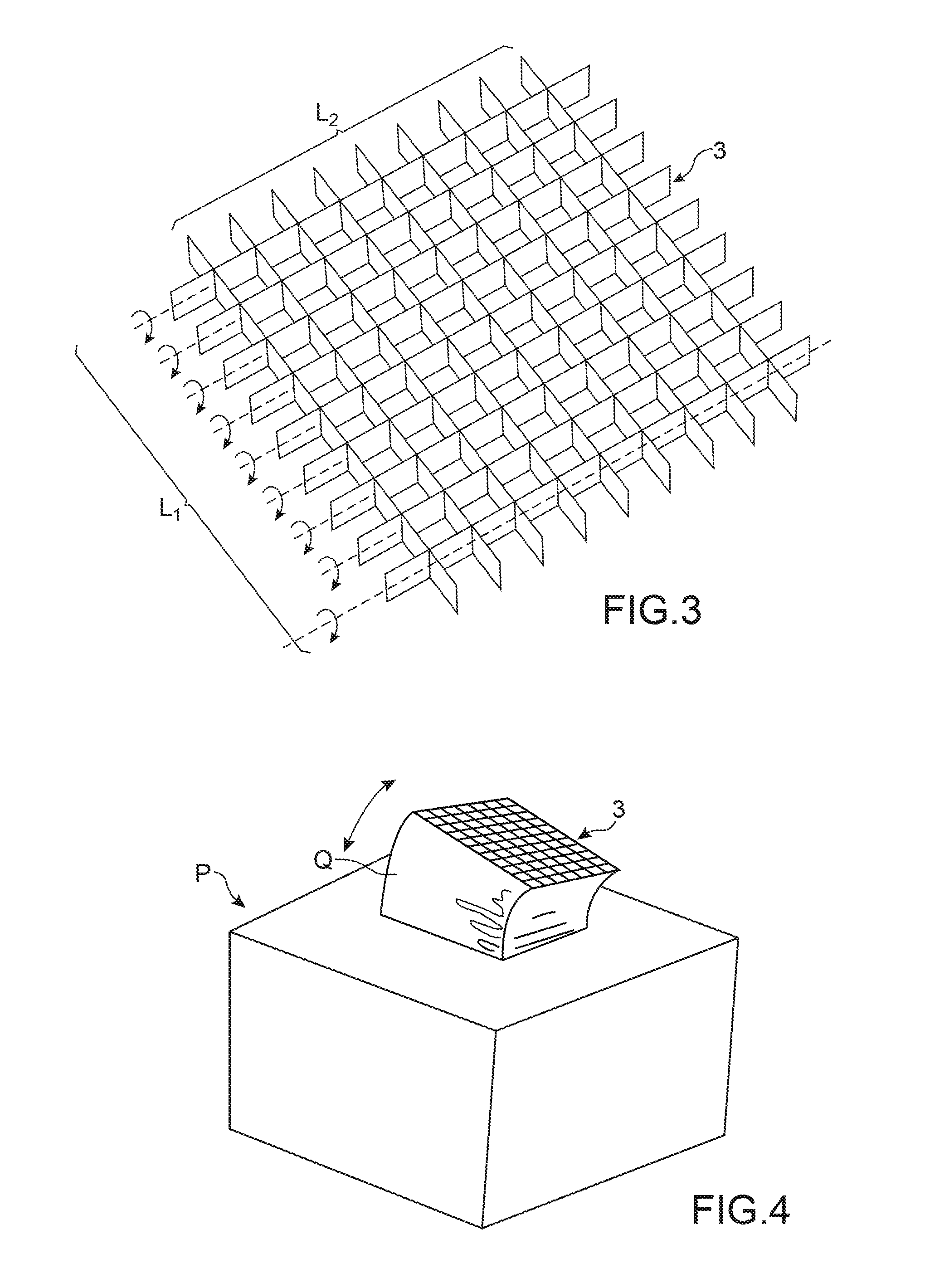
[0035]FIG. 3 shows an improvement to the hornet trap according to the invention.

[0036]According to the improvement to the invention, the opening means that allow hornets to enter the cavity can be oriented in order to give a better distribution of the call device A towards the hornets to be trapped.

[0037]According to the first embodiment of this improvement to the invention (see FIG. 3), some walls of the waveguides of the honeycomb type waveguide network can be oriented. The waveguides are then composed for example of two sets L1, L2 of metal strips perpendicular to each other, the metal strips of one of the two sets being oriented by pivoting them about their axes. The strips can be oriented about their axes by any method known in itself.

[0038]According to a second embodiment of this improvement to the invention (see FIG. 4), the opening means 3 through which hornets enter the cavity are located at the end of a deformable tube Q that opens up into one of the walls of the cavity. T...


PUM


Abstract

The invention relates to a hornet trap, characterised in that it comprises: a metal chamber (1) that defines a cavity (2), a wall of the chamber being provided with opening means (3) through which at least one hornet can enter the cavity, the opening means (3) being sized such that electromagnetic waves with a given frequency present in the cavity cannot escape from the cavity (2), means (4, 5, 6) of detecting the presence of at least one hornet in the cavity (2), and an electromagnetic wave source (S) capable of generating electromagnetic waves at the given frequency inside the cavity (2) when a hornet is detected in the cavity a call means (A).

Description

TECHNICAL FIELD AND PRIOR ART[0001]The invention relates to a hornet trap and more particularly a trap for Asian hornets.[0002]The invention is applicable to the field of eradication of pests harmful to biodiversity, and in the long term to human health.[0003]The Asian hornet is currently growing quickly in terms of the numbers and of geographic distribution. Asian hornets are not considered as pests in Asia because there are many natural predators for these insects. This is not the case on the European continent where their eradication is therefore necessary.[0004]At the present time, the technique used for elimination of Asian hornets consists of injecting an anaesthetic product into hornet nests and then when the insects have been anesthetised, to collect the nests and destroy them by incineration.[0005]This technique is complicated to apply, it is polluting and there is a risk for the persons doing the work. It is also possible that insects belonging to the nest will escape this...

Claims


Application Information

Patent Timeline
Patent Type & Authority Patents(United States)
IPC IPC(8): A01M1/02A01M1/04A01M1/22A01M1/10
CPCA01M1/226A01M1/02A01M1/023A01M1/026A01M1/04A01M1/106
Inventor RIBIERE-THARAUD, NICOLASBOURZEIX, MICHEL
Owner COMMISSARIAT A LENERGIE ATOMIQUE ET AUX ENERGIES ALTERNATIVES
Why Eureka
Try Eureka