Gamma-ray spectrometer

a gamma-ray spectrometer and gamma-ray technology, applied in the field of gamma-ray spectrometers, can solve the problems of poor optical design of large-volume detectors, difficult to accurately solve calibration of energy-loss spectra generated by pvt detectors, and increased difficulty in tasks

Active Publication Date: 2016-10-11
SYMETRICA
View PDF11 Cites 1 Cited by
  • Summary
  • Abstract
  • Description
  • Claims
  • Application Information

AI Technical Summary

Benefits of technology

[0018]According to a second aspect of the invention there is provided a method for calibrating a gamma-ray spectrometer, comprising the steps of: providing a gamma-ray spectrometer arranged to receive gamma-rays from a calibration source; the gamma-ray spectrometer comprising: a scintillator material optically coupled to two or more photomultipliers, the two or more photomultipliers being arranged to detect photons generated in the scintillator material associated with gamma-ray interactions between the scintillator material and gamma-rays received from the calibration source, wherein the two or more photomultipliers are operable to output respective detection signals associated with the gamma-ray interactions; detecting photons generated in the scintillator material associated with gamma-ray interactions between the scintillator material and gamma-rays received from the calibration source; selecting detection signals from one of the two or more photomultipliers; and stabilizing the gain of the photomultiplier that output the selected detection signals based on the detection signals.

Problems solved by technology

The sparseness of this data means that it is typical to sum the energy-loss spectrum from four or more large volume PVT detectors.
The problem of calibrating the energy-loss spectra generated by a PVT detector is difficult to solve accurately.
Often this task is made more difficult by the poor optical design of the large-volume detectors.
This means that the quality of the spectra are often so poor that the detailed features used in some calibration methods are difficult to implement.

Method used


Image

  • Gamma-ray spectrometer
  • Gamma-ray spectrometer

Examples


Embodiment Construction

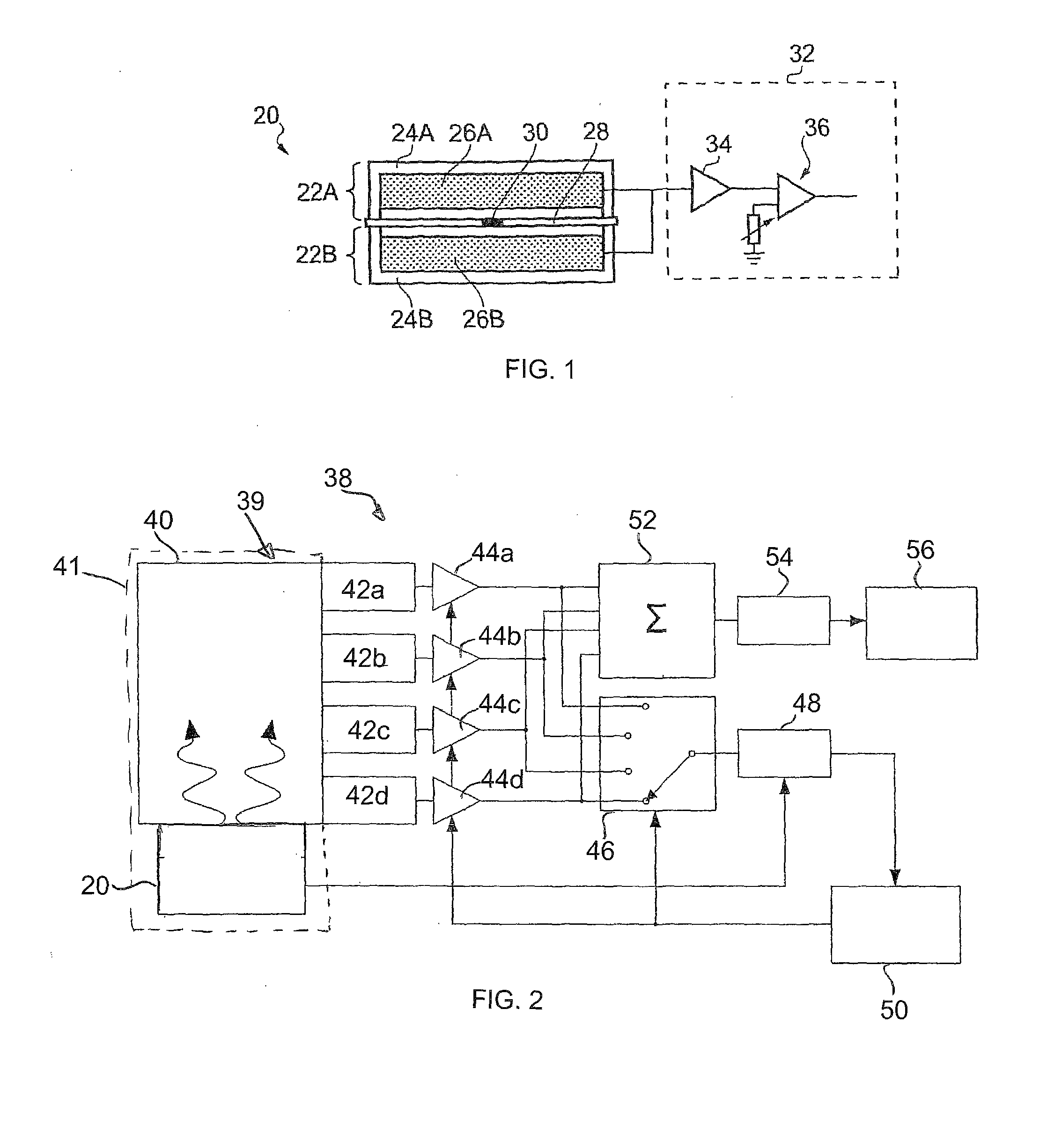
[0022]FIG. 1 schematically shows a calibration source 20 according to an embodiment of the invention. The calibration source is described in further detail in granted patent GB 2463707. The calibration source 20 is based around a deposit of radioactive material 30 comprising a radioactive isotope having a decay transition associated with emission of a radiation particle and a gamma-ray. In this example, the radioactive material comprises a salt of Na-22. Na-22 is associated with a radioactive transition that results in emission of a beta-plus particle (positron) having a maximum energy of around 545 keV, and a gamma-ray having an energy around 1274 keV. Subsequent matter-anti-matter annihilation of the positron further results in the emission of a pair of 511 keV gamma-rays. In this example the radioactive material 30 has an activity of around 100 Bq. This will of course reduce with time, with Na-22 having a half-life of around 2.6 years.

[0023]The radioactive material 30 is mounted ...


PUM


Abstract

An apparatus is described. The apparatus comprising a gamma-ray spectrometer arranged to receive gamma-rays from a calibration source, the gamma-ray spectrometer comprising: a scintillator material optically coupled to two or more photomultipliers, the two or more photomultipliers being arranged to detect photons generated in the scintillator material associated with gamma-ray interactions between the scintillator material and gamma-rays received from the calibration source, wherein the two or more photomultipliers are operable to output respective detection signals associated with the gamma-ray interactions; the apparatus further comprising: a switch coupled to receive the respective detection signals from the two or more photomultipliers and operable to select detection signals from one of the two or more photomultipliers; and a stabilization circuit coupled to the switch and operable to receive the selected detection signal of the respective photomultiplier and to stabilize the gain of the photomultiplier that output the selected detection signal based on the detection signals.

Description

BACKGROUND ART[0001]The invention relates generally to gamma-ray spectrometers.[0002]Large volume plastic gamma-ray spectrometers constructed using, for example, polyvinyltoluene or polystyrene scintillation material, are being accepted as valid detectors for screening large cargo containers, trucks and trains at ports and other border crossing points. GB 2437979 describes how such detectors might be designed in order to maximise the efficiency with which the scintillation light from a gamma-ray interaction can be collected and demonstrates how the variance in the light-collection efficiency can be minimised. GB 2418015 shows how the most probable spectrum of the incident gamma-rays could be derived from the recoded energy-loss spectrum. The quality of that incident spectrum is such that in many cases it is possible to identify the nature of the radioactivity detected in the cargo. In the radiation detection industry, one goal is to develop a polyvinyl toluene (PVT) can be doped wit...

Claims


Application Information

Patent Timeline
Patent Type & Authority Patents(United States)
IPC IPC(8): G01T1/40G01T1/36
CPCG01T1/40G01T1/362G01T1/203
Inventor MANSLOW, JOHNRAMSDEN, DAVID
Owner SYMETRICA
Why Eureka
Try Eureka