
Lever switch

a technology of lever switch and dead space portion, which is applied in the direction of contact engagement, emergency protective device, transportation and packaging, etc., can solve the problems that cannot be received inside a cosmetic part depending on the required design, and achieve the effect of high degree of freedom of utilization of dead space portion, convenient response and efficient arrangemen

Active Publication Date: 2016-10-11
ALPS ALPINE CO LTD
View PDF3 Cites 0 Cited by
  • Summary
  • Abstract
  • Description
  • Claims
  • Application Information

AI Technical Summary

Benefits of technology

The invention provides a lever switch that can easily respond to miniaturization and design requirements. By creating a dead space on one side of the switch, components can be efficiently arranged and utilized, allowing for easy response to different designs. The switch also has two types of input operations and a D-shaped cross-section, which improves operational efficiency and ease of recognition. Overall, the lever switch is designed to be more user-friendly and easy to operate.

Problems solved by technology

However, since the lever switch 900 described in Japanese Patent No. 4695310 has many components formed in a substantially symmetrical shape as viewed from the rotational axis, there is a concern that the structure as it is cannot be received inside a cosmetic part depending on the required designs.

Method used


Image

  • Lever switch
  • Lever switch
  • Lever switch

Examples


first embodiment

[0029]A lever switch 100 in a first embodiment will be described below.

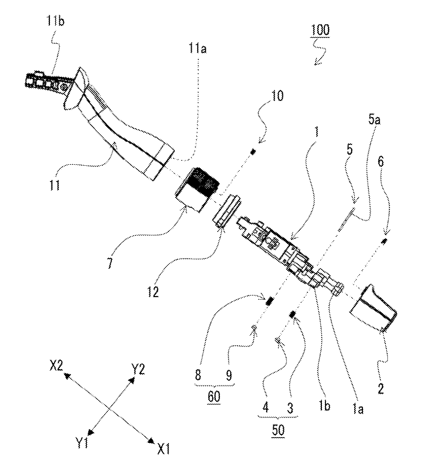
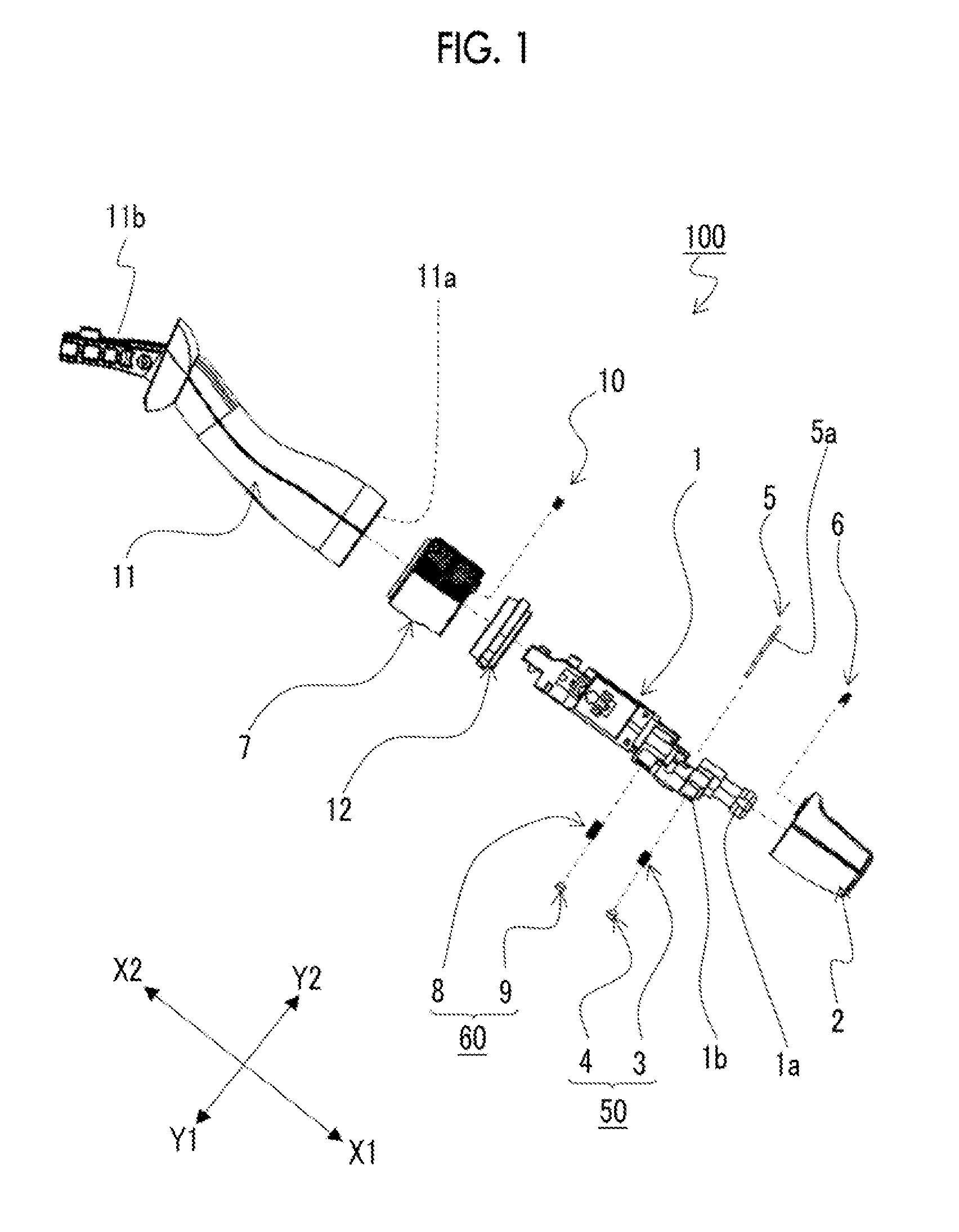
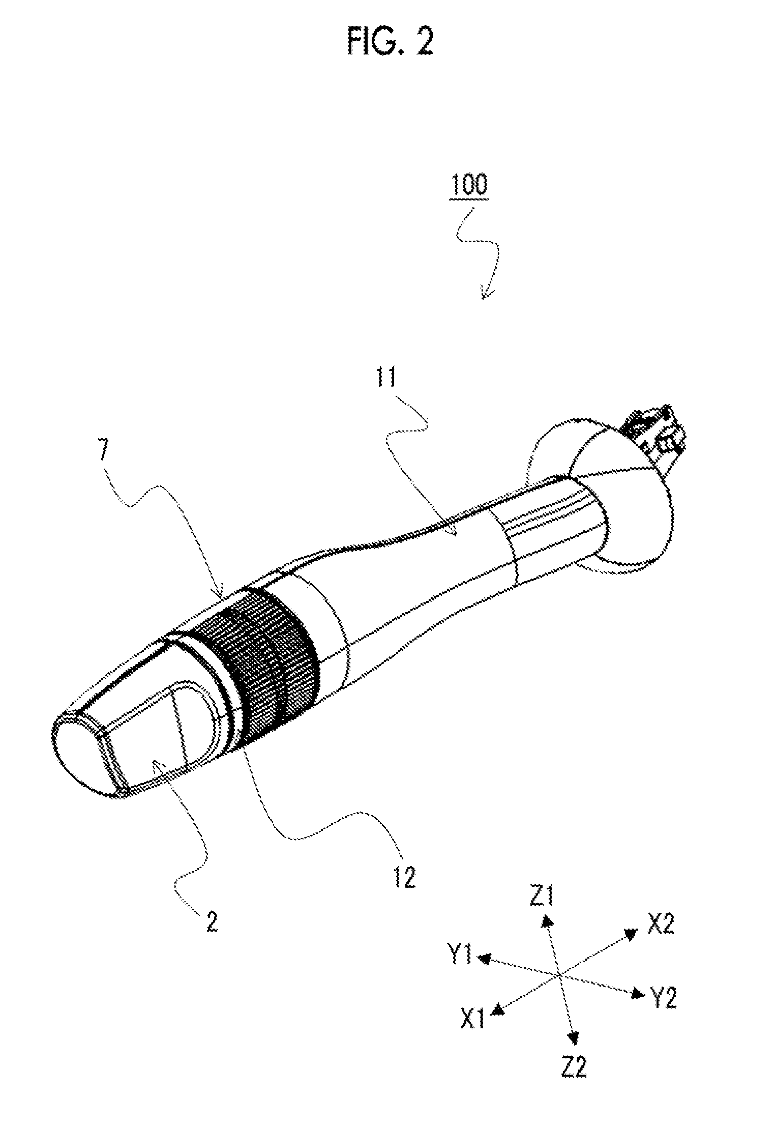
[0030]First, the configuration of the lever switch 100 in the present embodiment will be described with reference to FIGS. 1 to 10B. FIG. 1 is an exploded perspective view illustrating the configuration of the lever switch 100 in a first embodiment. FIG. 2 is a perspective view illustrating the appearance of the lever switch 100 in the first embodiment. FIGS. 3A and 3B are views illustrating a substrate 5 in the first embodiment; FIG. 3A is a perspective view illustrating one surface of the substrate 5, and FIG. 3B is a perspective view illustrating one surface of the substrate 5. FIG. 4 is a perspective view illustrating the appearance of a first slider 6 in the first embodiment. FIG. 5 is a perspective view illustrating the appearance of a second slider 10 in the first embodiment. FIG. 6 is a perspective view illustrating the appearance of a base member 1 in the first embodiment. FIGS. 7A and 7B are views illus...


PUM


Abstract

A lever switch has a base member, a first switch knob member, a first moderation mechanism, a substrate having a first contact member, and a first slider. The base member has a first supporting surface formed along an outer peripheral surface of a column centered on a rotational axis of the first switch knob member and a second supporting surface formed on one side across the rotational axis. The first switch knob member includes a first supported surface and a second supported surface, and the second supported surface is provided with a first cam portion. The first supported surface is rotatably supported on the first supporting surface, the second supported surface is rotatably supported on the second supporting surface, and the first slider is held on a side opposite to a side where the second supporting surface is provided across the rotational axis.

Description

CLAIM OF PRIORITY[0001]This application claims benefit of Japanese Patent Application No. 2013-212936 filed on Oct. 10, 2013, which is hereby incorporated by reference.BACKGROUND OF THE INVENTION[0002]1. Field of the Invention[0003]The present invention relates to a lever switch, and particularly, a lever switch that easily responds to miniaturization or to the required designs.[0004]2. Description of the Related Art[0005]As operating devices used for the operation of blinkers, wipers, or the like in automobiles, there are operating devices that are arranged near a steering wheel and formed in the shape of a lever. Among lever switches provided in such operating devices and used for various kinds of operation, lever switches designed to be easily pinched with the fingers are increasing being used in order to further improve operability.[0006]A lever switch described in the following Japanese Patent No. 4695310 is known as a related-art lever switch. Hereinafter, the lever switch des...

Claims


Application Information

Patent Timeline
Patent Type & Authority Patents(United States)
IPC IPC(8): H01H19/14H01H1/40B60Q1/14
CPCB60Q1/1476H01H19/14H01H1/40H01H2205/004H01H2231/026H01H2215/054
Inventor KIKUCHI, TSUYOSHI
Owner ALPS ALPINE CO LTD
Learn More