Thrust bearing structure and supercharger equipped with said thrust bearing structure

Active Publication Date: 2016-10-18
IHI CORP
View PDF16 Cites 13 Cited by
  • Summary
  • Abstract
  • Description
  • Claims
  • Application Information

AI Technical Summary

Benefits of technology

[0010]An object of the present invention is to provide a thrust bearing structure of a novel configuration which can secure high-level capacity against load and a supercharger equipped with the thrust bearing structure.
[0016]According to the present invention, it is possible to provide a thrust bearing structure of a novel configuration which can secure high-level capacity against load and a supercharger equipped with the thrust bearing structure.

Problems solved by technology

It is an urgent issue for a rotary machine to secure a high bearing performance against a thrust load.

Method used


Image

  • Thrust bearing structure and supercharger equipped with said thrust bearing structure
  • Thrust bearing structure and supercharger equipped with said thrust bearing structure
  • Thrust bearing structure and supercharger equipped with said thrust bearing structure

Examples


Embodiment Construction

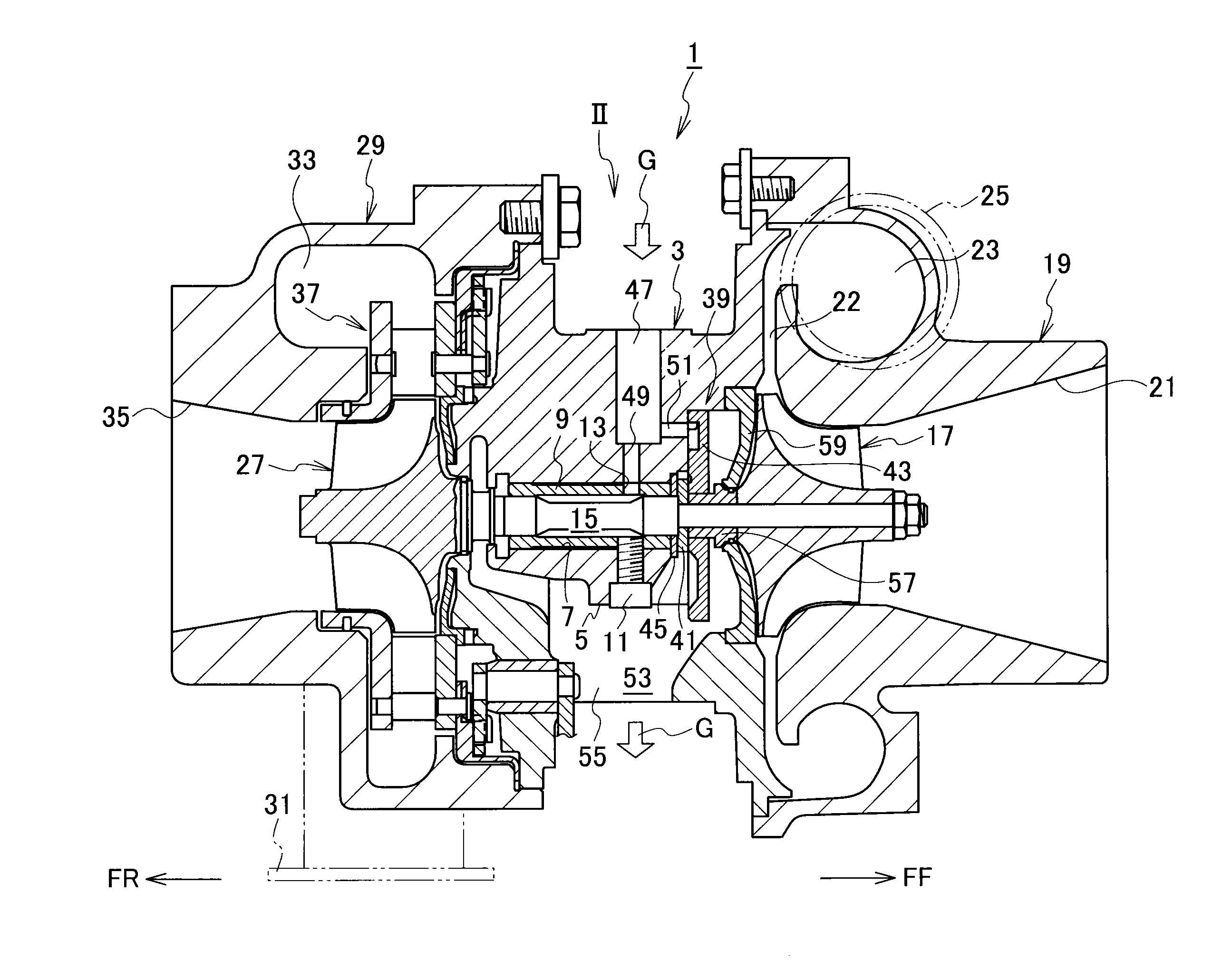
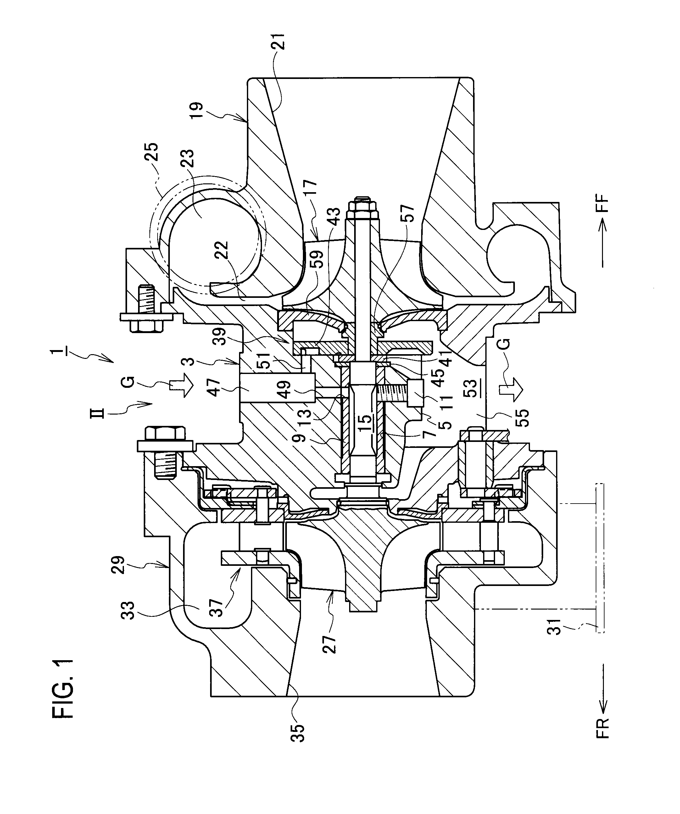
[0036]An embodiment of the present invention will be described with reference to FIG. 1 to FIG. 10. In the drawings, “FF” indicates a frontward direction and “FR” indicates a rearward direction. Note that these directions do not limit the present invention.

[0037]FIG. 1 and FIG. 2 show a supercharger 1 of this embodiment. The supercharger 1 is used in an automobile, for example, and is configured to supercharge (compress) air to be supplied to an engine (not illustrated) by using energy of an exhaust gas from the engine.

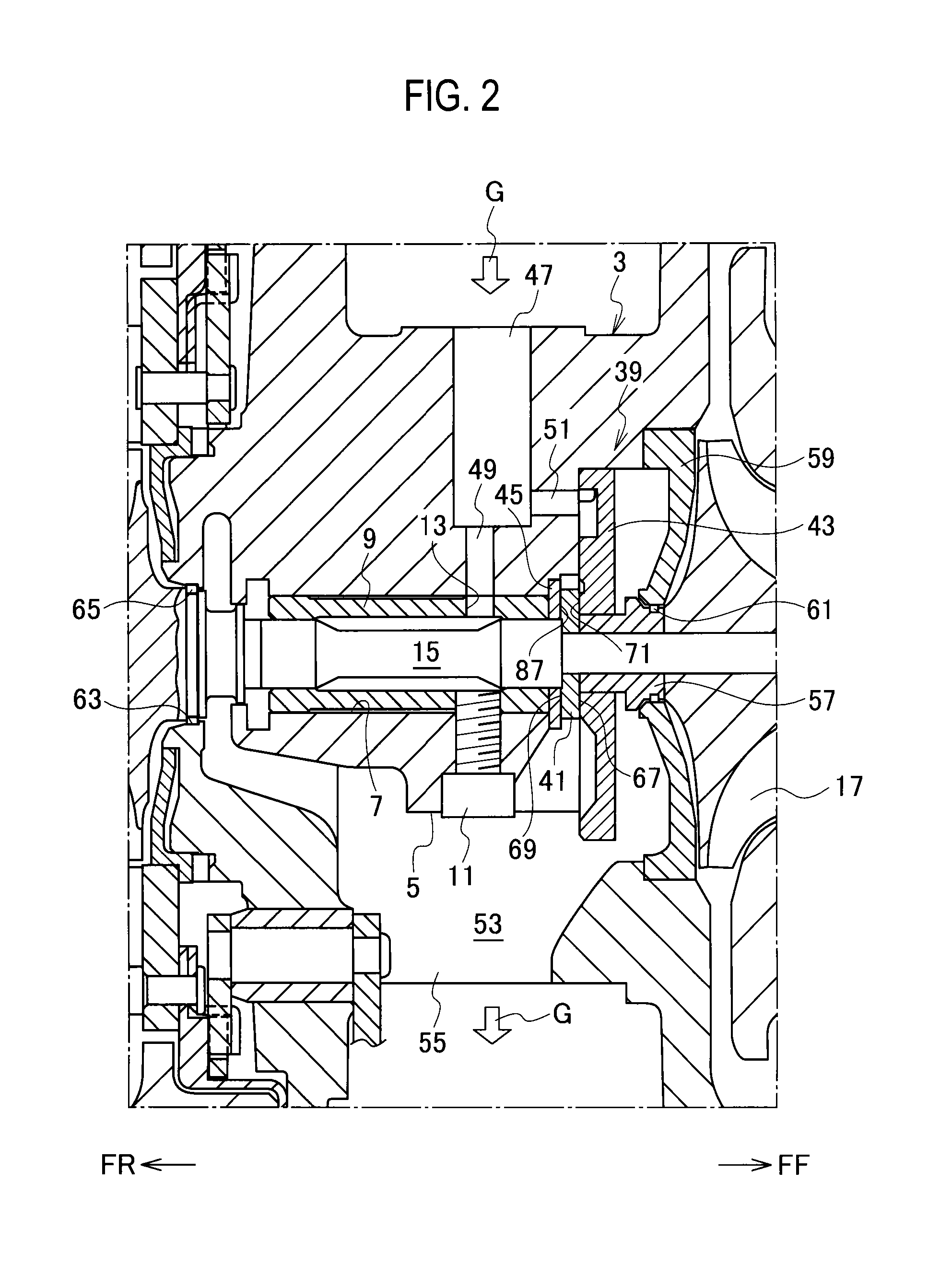
[0038]The supercharger 1 includes a housing (a bearing housing) 3. The housing 3 includes therein a support block 5 constituting part of the housing 3. An installation hole 7 extending in a front-rear direction is formed in the support block 5 in a penetrating manner.

[0039]A semi-floating metal 9 as an example of a radial bearing is installed inside the installation hole 7. A locking pin 11 is inserted into a side face of the semi-floating metal 9 through the support ...


PUM


Abstract

A thrust bearing structure is equipped with a thrust collar having a collar pad, and a thrust bearing having a bearing pad at a position corresponding to the collar pad on a surface facing the thrust collar. The bearing pad has a tapered section, and a land section continuously formed on the outer edge of the tapered section. Assuming that oil droplets are supplied between the bearing pad and the collar pad, and assuming that the rotation speed of a rotor shaft is constant, the tapered section would have a sloping surface formed in such a manner that a wall thickness gradually becomes thicker toward the downstream side along the trajectory of given oil droplets based on the centrifugal forces acting on the droplets due to the rotation of the rotor shaft.

Description

CROSS REFERENCE TO RELATED APPLICATIONS[0001]This application is a continuation application of International Application No. PCT / JP2012 / 060209, filed on Apr. 16, 2012, which claims priority to Japanese Patent Application No. 2011-099232, filed on Apr. 27, 2011, the entire contents of which are incorporated by references herein.BACKGROUND OF THE INVENTION[0002]1. Field of the Invention[0003]The present invention relates to a thrust bearing structure configured to bear a thrust load applied in an axial direction, and a supercharger equipped with the thrust bearing structure.[0004]2. Description of the Related Art[0005]A supercharger known as an example of rotary machines includes a housing, a rotor shaft rotatably provided to the housing, a compressor impeller attached to one end of the rotor shaft, and a turbine impeller attached to the other end of the rotor shaft. The compressor impeller compresses air by using a centrifugal force while the turbine impeller generates torque by usin...

Claims


Application Information

Patent Timeline
Patent Type & Authority Patents(United States)
IPC IPC(8): F04D29/057F16C32/06F16C33/10F16C17/04F02B39/14
CPCF04D29/057F16C17/047F16C32/0629F16C33/1075F02B39/14F16C2360/24F16C17/02F16C17/26F16C27/02F01D25/16F02B39/00F16C17/04F16C33/10F16C17/18
Inventor UNEURA, YUTAKA
Owner IHI CORP
Why Eureka
Try Eureka