Fluid line connector

a technology of connectors and fluid lines, applied in the direction of hose connections, pipe joints, fluid pressure sealed joints, etc., can solve the problems of compression of the flexible portion of the ferrule, achieve easy installation, facilitate radial compression of the ferrule, and enhance the ability of the ferrule to secure

Active Publication Date: 2016-10-18
AGS I PROP
View PDF26 Cites 8 Cited by
  • Summary
  • Abstract
  • Description
  • Claims
  • Application Information

AI Technical Summary

Benefits of technology

[0005]The fluid line connector of the present invention includes a main body with a profiled or varying-diameter inner surface that defines a fluid passageway. The profiled inner surface defines a series of circular stepped regions that allow the fluid line connector to be adapted for use on fluid lines of different diameters or sizes. An annular ferrule is partially positioned in an open end of the main body, and at least a portion of the ferrule is radially compressible to engage or impinge on the outer surface of a fluid line that is positioned in the fluid passageway of the main body. The fluid line is typically urged into abutment with one of the stepped regions prior to compressing the ferrule. An annular conduit coupler is attached to an outer surface of the main body, and has an inner surface that engages the ferrule to bias or urge the ferrule inwardly relative to the main body as the coupler is moved or tightened onto the body. This movement of the ferrule results in compression of the flexible portion of the ferrule due to engagement of corresponding ramped surfaces of the ferrule and the main body. By tightening the conduit coupler with a fluid line positioned in the main body, the ferrule is compressed into tight engagement with the fluid line, which helps secure the fluid line in the main body. Optionally, the fluid line connector may comprise a double-ended connector, such that two fluid lines having the same or different diameters may be coupled to one another using a single fluid line connector.
[0006]Optionally, the outer surface of the connector's main body includes a threaded outer portion, and the inner surface of the conduit coupler includes a threaded inner portion corresponding to the outer threaded portion of the main body, so that the conduit coupler and the ferrule are axially movable together relative to the main body via rotation of the conduit coupler about the threaded body. Optionally, the inner surface of the main body includes a seal-receiving portion for receiving an annular seal in an annular space defined between the inner surface of the main body and the outer surface of the fluid line. The ferrule may include a plurality of longitudinal slots in a circumferentially-spaced arrangement, to facilitate radial compression of the ferrule. The ferrule may further include a radially inwardly-directed annular shoulder at its compressible portion, for impinging on the outer surface of the fluid conduit, which enhances the ferrule's ability to secure the conduit or fluid line in the body of the connector.
[0007]Thus, the fluid line connector of the present invention provides for the secure repair of damaged fluid lines, such as those that may be found on a vehicle. The connector is adaptable for use on fluid lines of different diameters, and can also be used for connecting the ends of fluid lines to other couplings or fluid conduits. The present invention can provide a low-cost, easy-to-install, and leak-resistant repair, which resists inadvertent pull-out of the fluid line from the connector.

Problems solved by technology

This movement of the ferrule results in compression of the flexible portion of the ferrule due to engagement of corresponding ramped surfaces of the ferrule and the main body.

Method used


Image

  • Fluid line connector
  • Fluid line connector
  • Fluid line connector

Examples


Embodiment Construction

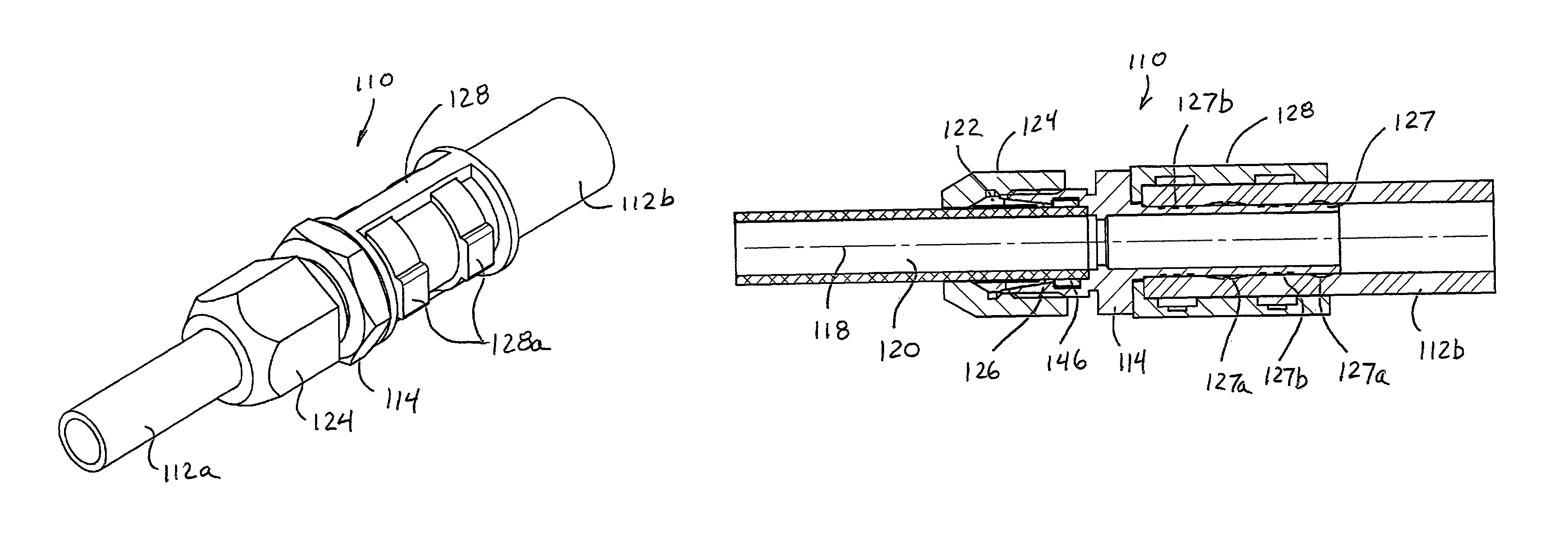
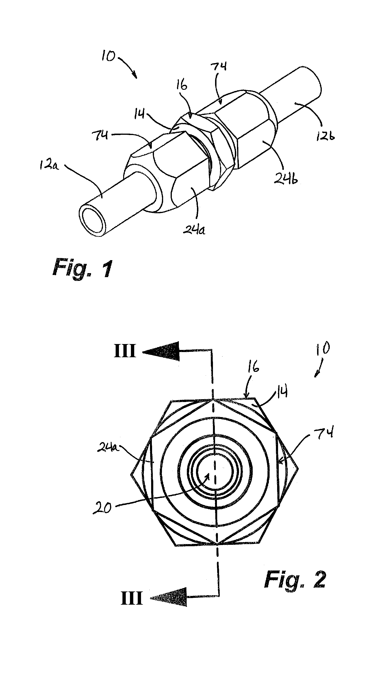
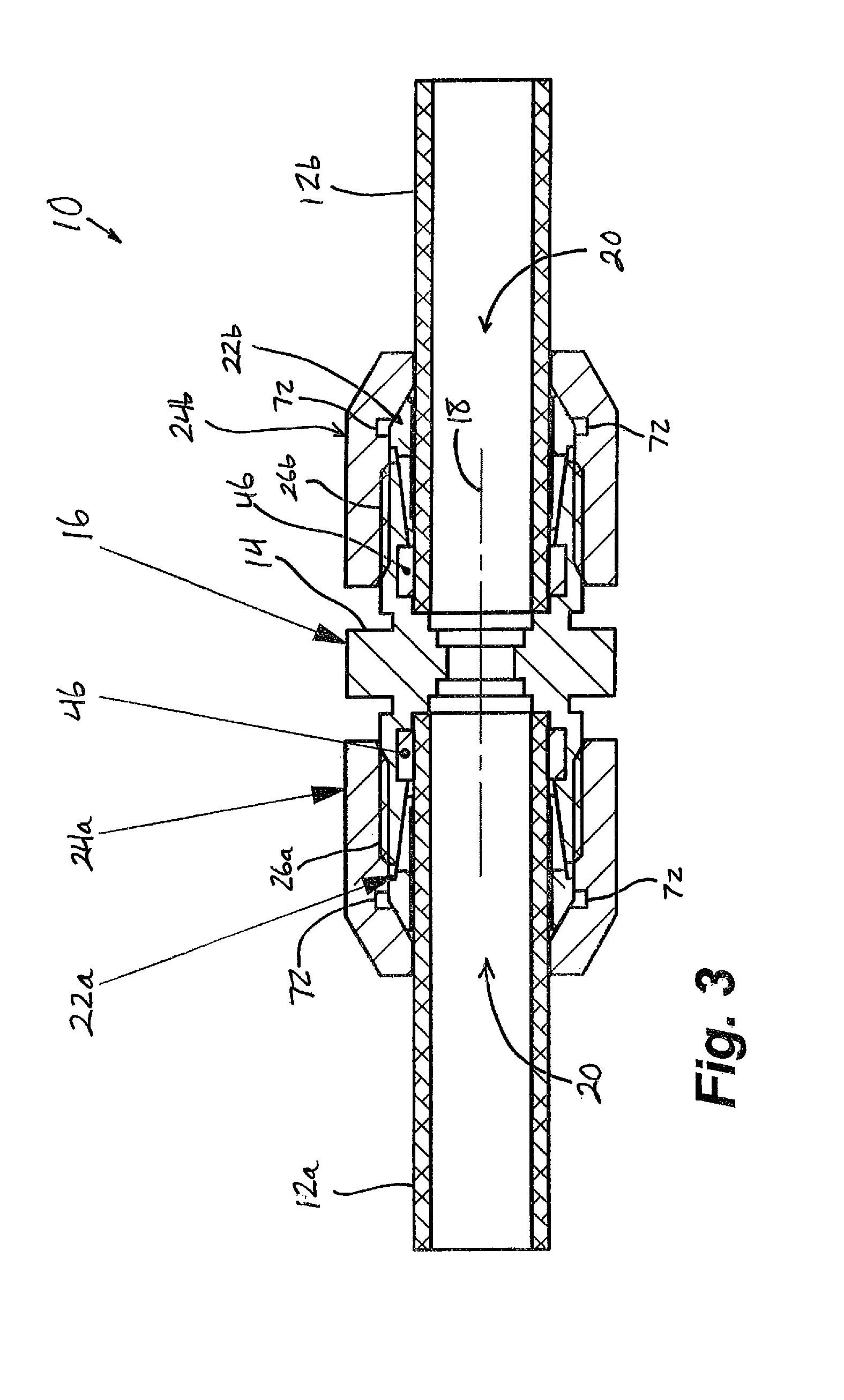
[0027]Referring now to the drawings and the illustrative embodiments depicted therein, a fluid line connector 10 is provided for the secure coupling of respective ends of fluid lines or conduits 12a, 12b (FIGS. 1 and 3). For example, the two fluid lines 12a, 12b may be formed from a single fluid line that was cut to remove a damaged section of the line. In the illustrated embodiment, fluid line connector 10 is symmetrical about a lateral axis or a plane that passes through a main body 14 at a central gripping portion 16 (which may typically have a non-circular outer surface, such as a hexagonal shape as shown). Referring to FIG. 3, fluid line connector 10 has a longitudinal central axis 18 along which a fluid passageway 20 is defined through the connector (FIGS. 2 and 3). Two ferrules 22a, 22b are positioned on respective sides of main body 14, and a conduit coupler or collar 24a, 24b couples the respective ferrules 22a, 22b to main body 14, to secure fluid lines 12a, 12b in fluid l...


PUM


Abstract

A fluid line connector facilitates the rapid and inexpensive replacement or repair of damaged portions of a fluid line or conduit, such as a vehicular refrigerant line, oil line, fuel line, or the like. The fluid line connector includes a main body that can accommodate different sizes of fluid lines, with ferrules and conduit couplers attached at opposite ends of the main body. The conduit couplers, ferrules, and seals cooperate with the main body to retain and seal the respective open ends of the fluid line in the connector, thus creating a secure and sealed junction or connection along a fluid conduit.

Description

CROSS REFERENCE TO RELATED APPLICATION[0001]The present application claims the benefit of U.S. provisional application Ser. No. 61 / 494,575, filed Jun. 8, 2011, which is hereby incorporated herein by reference in its entirety.FIELD OF THE INVENTION[0002]The present invention relates generally to couplers or connectors for attaching the ends of fluid lines to one another or to other fluid couplings.BACKGROUND OF THE INVENTION[0003]Fluid lines, conduits, hoses, and the like are commonly used for conveying vehicular fluids from one portion of a vehicle to another. Such conduits may be associated with fuel, engine and transmission oils and other lubricants, power steering fluid, coolants or refrigerants, hydraulic brake fluid, shock absorber fluid, ride height control fluid, and the like. When such fluid lines require repair, such as due to pinhole leaks, cracks, impact damage, or the like, it is generally desirable and significantly faster and more economical to repair the damaged secti...

Claims


Application Information

Patent Timeline
Patent Type & Authority Patents(United States)
IPC IPC(8): F16L17/00F16L19/10
CPCF16L19/10F16L33/2071F16L33/224
Inventor PEIRCE, JOHN M.
Owner AGS I PROP
Why Eureka
Try Eureka