
Adaptable foam roller

a foam roller and adaptable technology, applied in the field of paint tools, can solve the problems that the sheath may not be adhesively attached to the core, and achieve the effects of improving cleaning, manufacture and adaptability

Inactive Publication Date: 2006-11-09
FOAMPRO MFG
View PDF6 Cites 9 Cited by
  • Summary
  • Abstract
  • Description
  • Claims
  • Application Information

AI Technical Summary

Benefits of technology

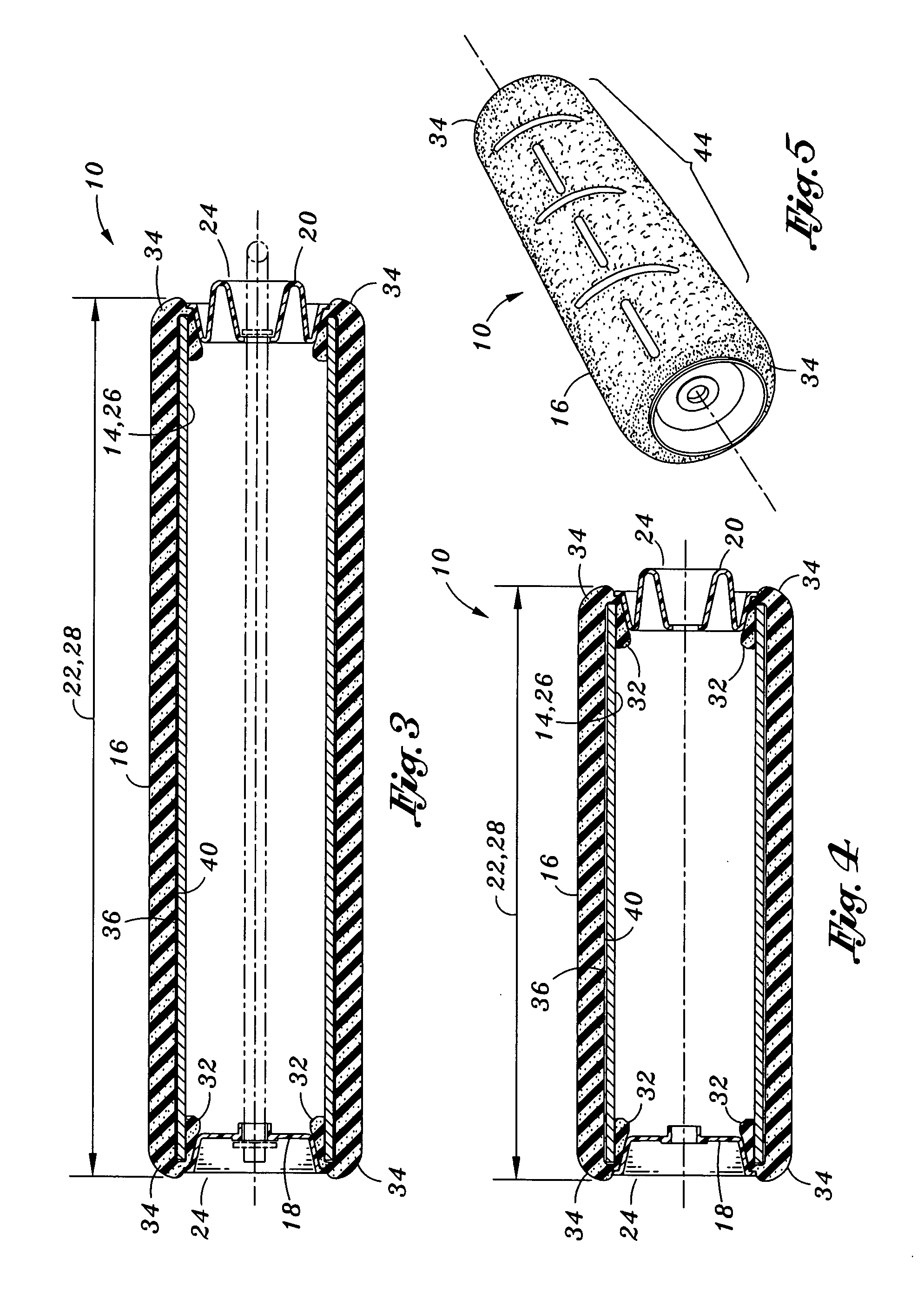
[0010] In accordance with an embodiment of the present invention, a composite paint roller is provided for improving ease of cleaning, manufacture and adaptability. The roller comprises an elongate cylindrical core, a sheath, and first and second end caps. The core is preferably formed having a tubular configuration and defines a core length and opposing open ends. The sheath is removably mountable about the core and defines an axial length and opposing sheath ends. The axial length of the sheath is preferably greater than the core length with the opposing sheath ends being foldable and axially insertable into the opposing open ends. The first and second end caps each are attachable to the opposing open ends to secure the opposing sheath ends within the opposing open ends.
[0011] In accordance with an aspect of the present invention, the sheath is preferably fabricated from a resilient material. Due to the resiliency of the sheath, insertion of the sheath into the opposing open ends facilitates and produces a radial compression of the sheath adjacent the opposing open ends. The radial compression of the sheath results in the creation of opposing beveled ends of the roller.
[0014] In accordance with another implementation of the present invention, a composite paint roller is provided for improving ease of cleaning, manufacture and adaptability. The roller comprises an elongate cylindrical core defining a core outer diameter, a core outer surface, a core length, and opposing open ends; a sheath being removably mountable about the core and being fabricated from a resilient material, the sheath defining a sheath inner diameter, a sheath inner surface, an axial length, and opposing sheath ends, the sheath inner diameter being less than the core outer diameter with the sheath being stretchable to axially slide onto the core with the sheave inner surface being frictionally engaged to the core outer surface, the axial length being greater than the core length with the opposing sheath ends being foldable and axially insertable into the opposing open ends to produce a radial compression of the sheath adjacent the opposing open ends, the radial compression creating opposing beveled ends of the roller; and first and second end caps each being attachable to the opposing open ends to secure the opposing sheath ends within the opposing open ends, the first and second end caps each defining a cap periphery including a plurality of radially-spaced tooth projections, the tooth projections of each cap being sized and configured to radially compress the opposing sheath ends within the opposing open ends.
[0017] In an implementation of the method, the sheath is fabricated from a resilient material. The inserting step may further include forming opposing beveled ends upon insertion of the opposing sheath ends into the opposing open ends. Insertion of the opposing sheath ends facilitates a radial compression of the resilient sheath adjacent the opposing open ends. This radial compression creates the opposing beveled ends of the roller.

Problems solved by technology

In this regard, the sheath may not adhesively affixed to the core.

Method used


Image

  • Adaptable foam roller
  • Adaptable foam roller
  • Adaptable foam roller

Examples


Embodiment Construction

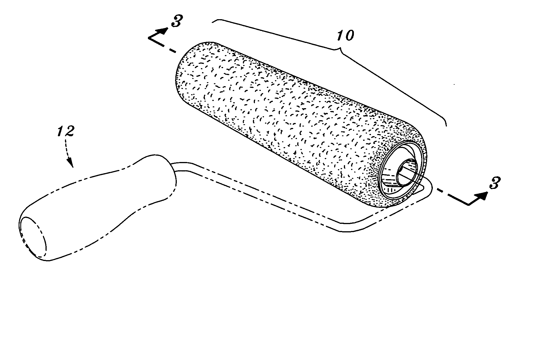
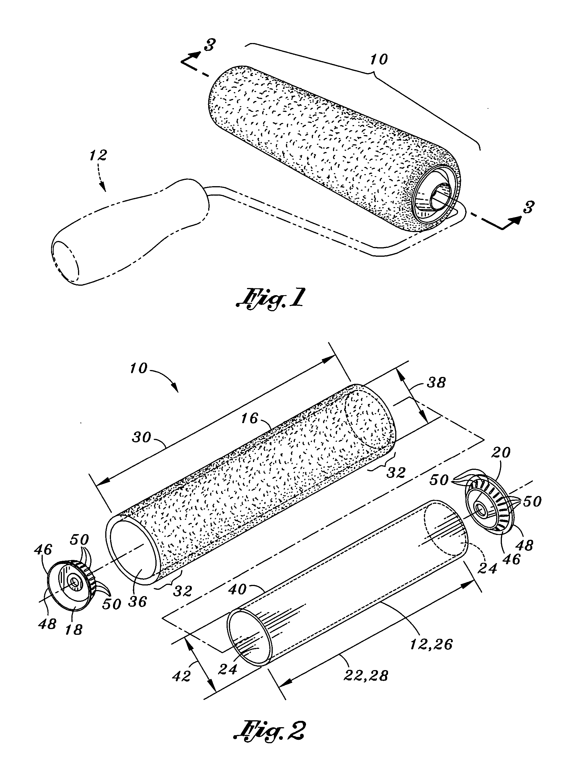
[0028] Referring now to the drawings wherein the showings are for purposes of illustrating the preferred embodiments of the present invention only and not for purposes of limiting the same, FIG. 1 is a perspective view of a composite paint roller 10 attached to a paint roller assembly 12. According to various aspects of the present invention, the roller is provided for improving ease of cleaning, manufacturing and adaptability of the same. The roller comprises an elongate cylindrical core 14, a sheath 16, and first and second end caps 18, 20.

[0029] Referring now to FIG. 1, the core is preferably formed having a tubular configuration and defines a core length 22 and opposing open ends 24. In an embodiment shown in FIGS. 2-4, the core may be a hollow tubular core 26. However, in other embodiments of the present invention, the core may be a solid core, or variations thereof (such as incorporating internal structural members). Additionally, the core may be manufactured having various l...


PUM

PropertyMeasurementUnit
lengthsaaaaaaaaaa
lengthaaaaaaaaaa
lengthaaaaaaaaaa

Abstract

A composite paint roller is provided for improving ease of cleaning, manufacture and adaptability of the same. The roller comprises an elongate cylindrical core, a sheath, and first and second end caps. The sheath is removably mountable about and frictionally engageable to the core. The core defines a core length and opposing open ends. The sheath defines an axial length and opposing sheath ends. The axial length of the sheath is greater than the core length with the opposing sheath ends being foldable and axially insertable into the opposing open ends to produce a radial compression of the sheath adjacent the opposing open ends. The radial compression creates opposing beveled ends of the roller. The first and second end caps each are attachable to the opposing open ends to secure the opposing sheath ends within the opposing open ends.

Description

CROSS-REFERENCE TO RELATED APPLICATIONS [0001] Not Applicable STATEMENT RE: FEDERALLY SPONSORED RESEARCH / DEVELOPMENT [0002] Not Applicable BACKGROUND OF THE INVENTION [0003] The present invention relates generally to painting tools. More specifically, the present invention is directed to a composite foam / fabric roller for improving the ease of cleaning, manufacture, and adaptability of the roller. [0004] There is currently known in the art a wide variety of products and processes for applying paint, varnish, adhesives and other coatings (collectively referred to herein as “paint”). These products may include, inter alia, spray guns, fabric rollers, bristle hair brushes, and rollers and brushes fabricated from foam materials. Generally, these products come in a variety of sizes and configurations in order to accommodate different needs based on application requirements. For example, a paint roller may vary in length, such as 3″, 4″, 6″, 7″ or 9″, and may also be available in varying ...

Claims


Application Information

Patent Timeline
Patent Type & Authority Applications(United States)
IPC IPC(8): B05C17/00
CPCY10T29/49826B05C17/0207
Inventor ISAAC, GREGORY J.
Owner FOAMPRO MFG
Learn More