
Display apparatus, source device and display system

a display apparatus and source device technology, applied in the field of display apparatus, can solve the problems of inability to perform judgment such as whether to rotate the image, inability to automatically remove the display device, and unclear orientation of the image received by the display apparatus

Active Publication Date: 2016-10-25
SHARP KK
View PDF12 Cites 4 Cited by
  • Summary
  • Abstract
  • Description
  • Claims
  • Application Information

AI Technical Summary

Benefits of technology

The present invention is a display apparatus that includes a display screen and an image processing portion. The display apparatus includes an orientation detecting portion that detects the orientation of the upper or lower part of the display screen and a receiving portion that receives an image signal carrying information about the orientation of the transmission image and the presence or absence of black band parts. The image processing portion applies rotation processing to align the orientation of the display screen with the orientation of the transmission image, scaling processing to maximize the display screen with an aspect ratio maintained, and black-band processing to add or remove black band parts, based on the orientation detection and the state information. The display apparatus also includes a touch sensor that outputs touch information indicating a user's touch position on the display screen, and the display apparatus performs coordinate conversion to align the touch information with the transmission image. The technical effects of the invention include improved image quality, improved user experience, and improved information sharing and utilization.

Problems solved by technology

However, since a size and an aspect ratio of an image that is transferred with the HDMI specification or the MHL specification from a mobile terminal apparatus are fixed to be landscape, in a conventional display apparatuses including the image display apparatus described in Japanese Laid-Open Patent Publication No. 2005-221634, an orientation of an image received by the display apparatus is unclear and it is impossible to perform judgment such as whether to rotate the image and whether to add black band parts on a display apparatus side.
Further, black band parts are sometimes added to an output image from the mobile terminal apparatus, and even when display with the black band parts removed as unnecessary parts is desired in the display apparatus, there is no information showing whether to be the output image with the black band parts added or the output image without addition on the display apparatus side, thus making it also impossible to remove them automatically.
In this using case, if processing such as rotation and addition of black band parts is executed for an output image from the mobile terminal apparatus freely on the display apparatus side, a touch coordinate detected by the display apparatus is deviated from that of an output video of the mobile terminal apparatus, thus making it impossible to perform an operation correctly even if the touch information is returned to the mobile terminal apparatus as it is.

Method used


Image

  • Display apparatus, source device and display system
  • Display apparatus, source device and display system
  • Display apparatus, source device and display system

Examples


first embodiment

(First Embodiment)

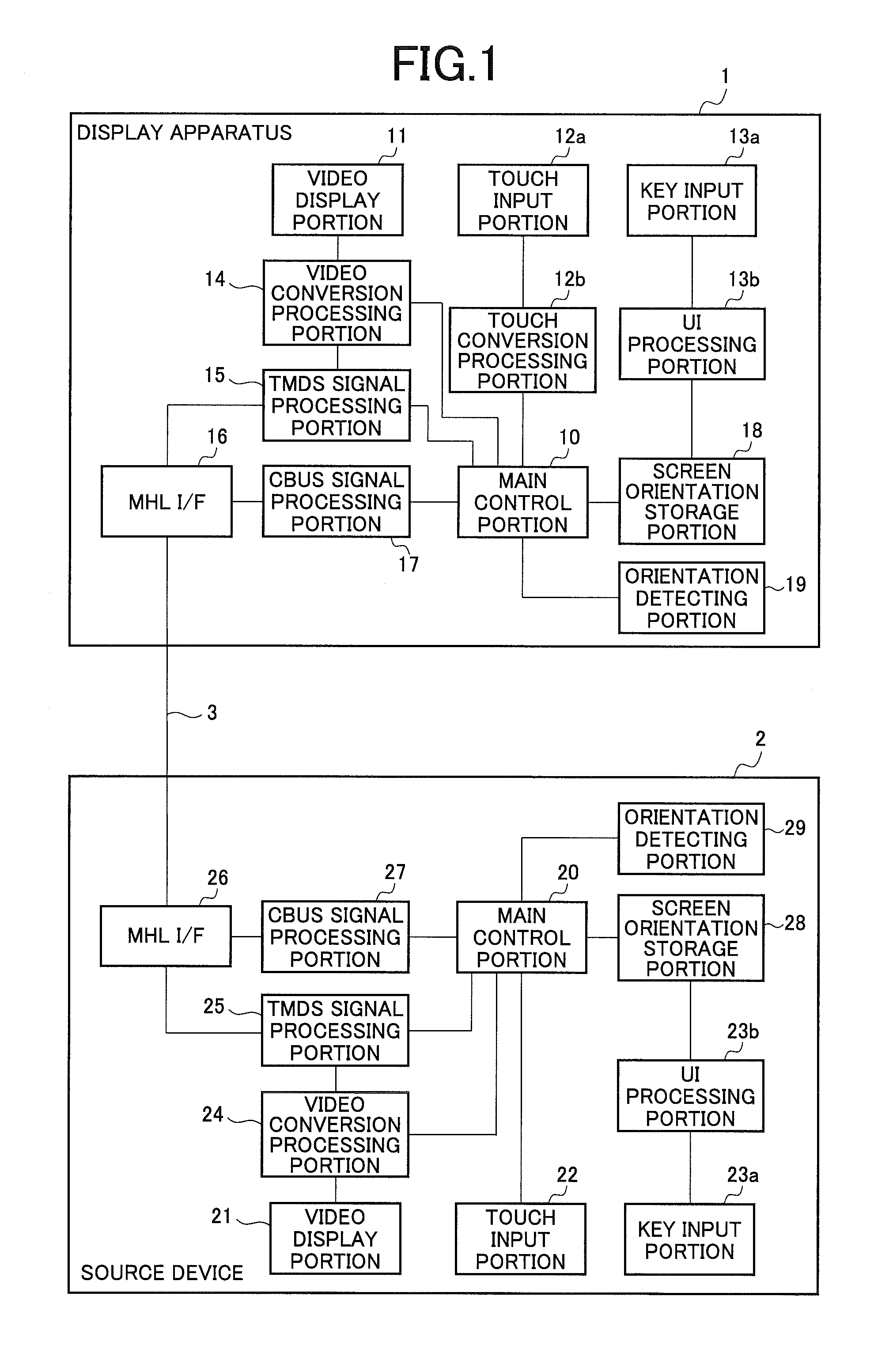
[0039]FIG. 1 is a block diagram showing an exemplary configuration of the display system according to the present invention.

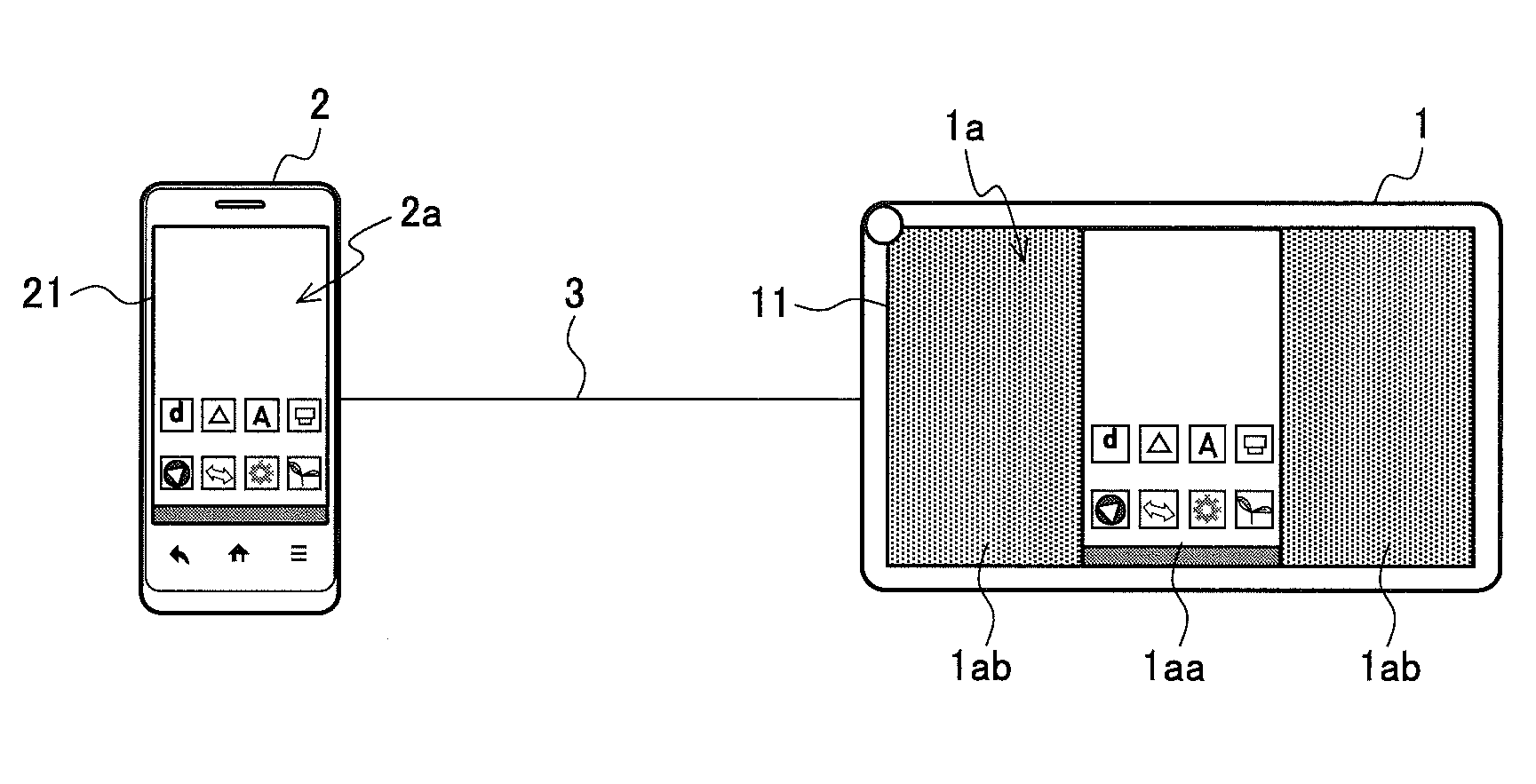
[0040]In the display system exemplified in FIG. 1, a display apparatus 1 that functions as a sink device and a source device 2 are connected with an MHL cable 3, and an image (hereinafter, video) is able to be transmitted from the source device 2 to the display apparatus 1 via the MHL cable 3.

[0041]The display apparatus 1 is provided with a display portion that displays an image, a receiving portion that receives an image signal (video signal) transmitted (transferred) from the source device 2 and an image processing portion, and display an image processed by the image processing portion on the display portion. Note that, such display control may be performed, for example, by a control portion of the display apparatus 1.

[0042]Further, the image processing portion applies image processing such as rotation processing, scaling processing and blac...

second embodiment

(Second Embodiment)

[0133]Next, description will be given for another exemplary processing of the display apparatus 1 with reference to FIG. 6, as a second embodiment of the present invention. FIG. 6 is a diagram explaining another exemplary processing of the display apparatus 1.

[0134]The display apparatus 1 of the present embodiment is characterized by having a touch function as exemplified in FIG. 1. That is, the display apparatus 1 has a touch sensor that outputs touch information showing a position touched by a user operation at a display portion such as the video display portion 11.

[0135]In the case of the display apparatus 1 with the touch function like this, when rotation processing, scaling processing or black-band processing is applied for a transmission image as described above on the display apparatus 1 side, if touch information is transferred as it is, the source device 2 side has a deviation from the display screen of a video display portion 21.

[0136]For example, descri...

third embodiment

(Third Embodiment)

[0140]Next, description will be given for another exemplary processing of the display system of FIG. 1 with reference to FIG. 7, FIG. 8A and FIG. 8B, as a third embodiment of the present invention. FIG. 7 is a flowchart explaining another exemplary processing of the display apparatus 1. In addition, FIG. 8A and FIG. 8B are diagrams explaining an example of negotiation processing between devices applicable in the display system of FIG. 1.

[0141]In the first and second embodiments, a case where an orientation of an actual image in a transmission image is necessarily matched with an orientation of the display apparatus 1 whether or not the source device 2 has black band parts added is shown. In the present embodiment, however, an orientation in which the display apparatus 1 is installed (orientation of the display screen) is able to be set by user input to the source device 2 side.

[0142]Of course, though a user may be caused to operate the source device 2 for direct in...


PUM


Abstract

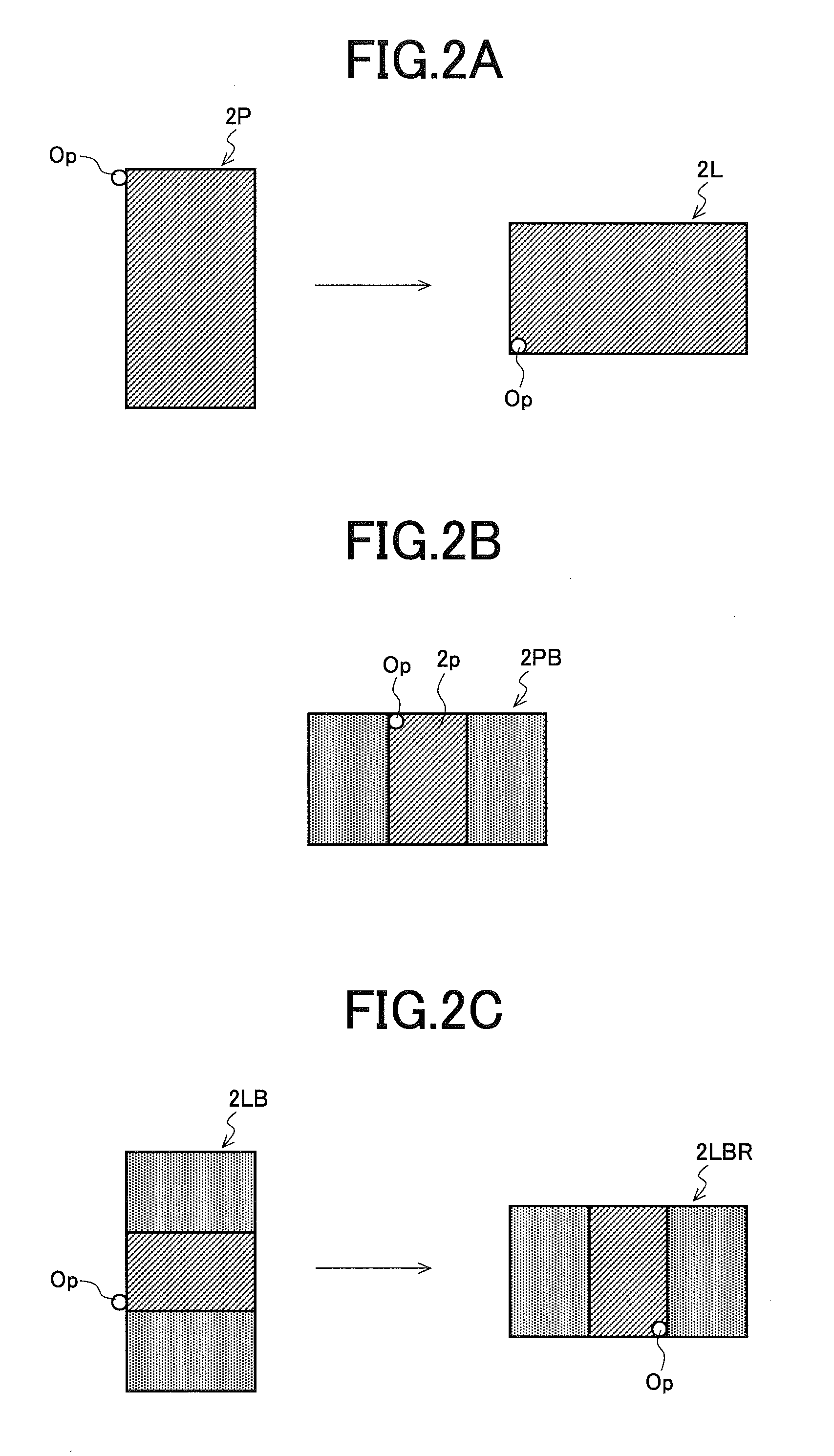
A display apparatus includes an orientation detecting portion, a receiving portion and an image processing portion. The orientation detecting portion detects an orientation of an upper part or a lower part of a display screen of a display portion. The receiving portion receives an image signal transmitted from a source device and state information (information showing an orientation of an upper part or a lower part of the transmission image indicated by the image signal and presence / absence of black band parts). The image processing portion applies, to the transmission image, rotation processing such that the orientation of the upper part or the lower part of the display screen coincides with the orientation of the upper part or the lower part of the transmission image, scaling processing, and / or black-band processing for adding or removing black band parts, according to a detection result of the orientation detecting portion and the state information.

Description

CROSS-NOTING PARAGRAPH[0001]This non-provisional application claims priority under 35 U.S.C. §119(a) on Patent Application No. 2013-203494 filed in JAPAN on Sep. 30, 2013, the entire contents of which are hereby incorporated herein by reference.FIELD OF THE INVENTION[0002]The present invention relates to a display apparatus, a source device and a display system, and more specifically to a display apparatus that displays an image transmitted from a source device, the source device and a display system provided with the display apparatus and the source device.BACKGROUND OF THE INVENTION[0003]Some mobile terminal apparatuses such as a smartphone, a mobile PC (Personal Computer) and a tablet terminal are provided with a video output terminal of a High-Definition Multimedia Interface (HDMI: registered trademark, the same hereinafter) specification or a Mobile High-definition Link (MHL: registered trademark, the same hereinafter) specification, and configured so as to be able to output an...

Claims


Application Information

Patent Timeline
Patent Type & Authority Patents(United States)
IPC IPC(8): G06T3/60
CPCG06T3/60G06T3/606
Inventor URATANI, OSAMUIMANISHI, SEIJI
Owner SHARP KK
Learn More