Image processing device, image processing method, and image processing program
a technology of image processing and image processing method, applied in the direction of color signal processing circuit, solid-state device signal generator, picture signal generator, etc., can solve the problem of not bringing about a sufficient correction effect, and achieve the effect of accurate differentiation
- Summary
- Abstract
- Description
- Claims
- Application Information
AI Technical Summary
Benefits of technology
Problems solved by technology
Method used
Image

Examples
embodiment 1
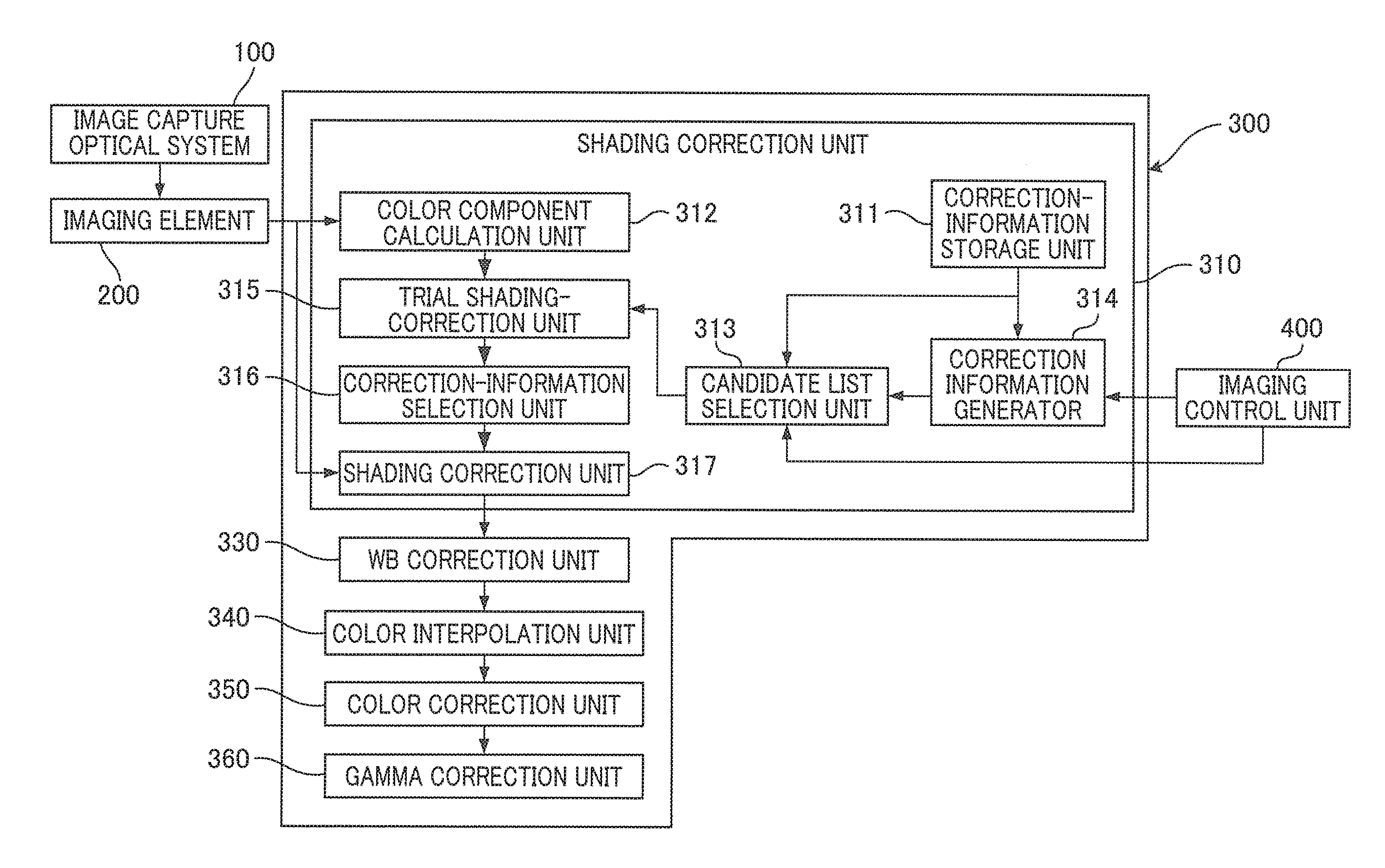
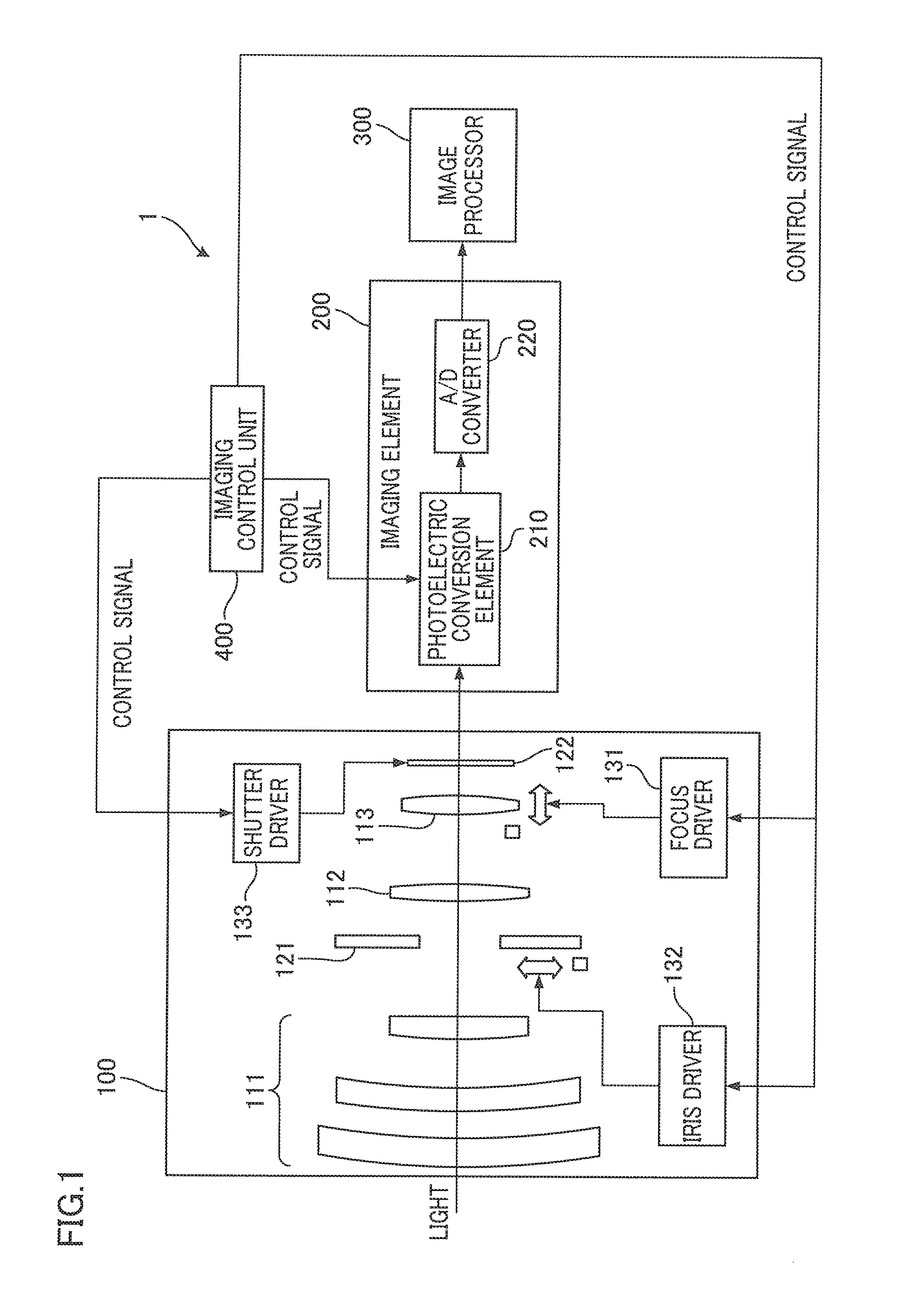
[0024]The following describes Embodiment 1 of the present invention. As shown in FIG. 1, an imaging device 1 includes: an image capture optical system 100 configured to guide and form a subject image on an imaging element 200; the imaging element 200 configured to conduct photoelectric conversion to the subject image formed, and output image data; an image processor 300 configured to conduct a predetermined image processing to the image data output from the imaging element 200, and reproduce the subject image; and an imaging control unit 400 configured to control the image capture optical system 100 and the imaging element 200. Image data of a still image is generated from the image data corresponding to an image of one frame output from the image processor 300, and moving picture data is generated from image data corresponding to images of multiple frames output time-sequentially from the image processor 300.
[0025]The image capture optical system 100 includes: a front lens set 111 ...
second embodiment
[0078]FIG. 10 shows an example case where color shading correction is performed to image data of a subject presenting a single color, with correction information associated with three light-sources that are: a light-source A, a light-source B, and a light-source C. FIG. 10(a) and FIG. 10(b) show a case where color shading is performed with correction information associated with the light-source A. This is an excessive correction and the Ave (R / G) tends to increase with an increase in the distance x, as shown in FIG. 10(a). The traversal axis of the graph in FIG. 10(a) indicates the distance from the center of the light axis, and therefore corresponds to the axis along a tangential direction. Therefore, the difference in Ave (R / G) of adjacent plots in the graph corresponds to the gradation value. The arrows in FIG. 10(a) each indicate the magnitude and the direction of the gradation. FIG. 10(b) is a histogram aggregation related to correction result of FIG. 10 (a), in which blocks ar...
first embodiment
[0097]In the above first Embodiment, when the maximum frequency among the plurality of classes related to a light-source with which the maximum frequency is the highest is not more than a predetermined value, the shading correction unit 317 determines that the reliability of the correction information selected by the correction-information selection unit 316 is low, and performs color shading correction on image data, based on adjusted correction information which is the correction information selected by the correction-information selection unit 316, having been adjusted. In addition to the above, when the ratio of the maximum value among the aggregated values of the plurality of classes to the aggregation parameter is not more than a predetermined magnitude, the shading correction unit 317 determines that the reliability of the correction information selected by the correction-information selection unit 316 is low, and performs color shading correction on image data, based on adju...
PUM
 Abstract
Description
Claims
Application Information