Monitoring Particles in a Fluid Stream

Inactive Publication Date: 2008-11-20
TELEDYNE INSTR INC
View PDF11 Cites 47 Cited by
  • Summary
  • Abstract
  • Description
  • Claims
  • Application Information

AI Technical Summary

Benefits of technology

[0034]Such an apparatus enables the flow force and the corrosion to be monitored on the same target surface, t

Problems solved by technology

In such systems, the particles may influence erosion, erosion/corrosion and/or corrosion of the conduit surface, potentially leading to breaches of the conduit by the fluid.
When a particle impacts the sample element in this way, it may corrode the sample element and therefore change the thickness and hence the electrical resistance of the sample element.
In addition to corrosion, excessive numbers of particles entrained in a fluid may cause blockage of the fluid flow through the conduit.
However, some particle impacts may not cause corrosion due to insufficient energy and/or a combination of mechanical properties of both particle and surface, potentially transferring all impulse momentum into the elastic region of the material, hence resulting in no permanent deformation or damage of the impacted surface.
Or conversely, particulate matter of low mass but high hardness and sharp edges can cause high corrosion rates.
Methods to overcome this have been to use softer element materials but such materials are not representative of the pipe, and therefore cannot be used to measure the extent of actual pipe corrosion.
In addition the particle velocity will affect the corrosion rate, which is another reason that the particle mass is not easy to

Method used


Image

  • Monitoring Particles in a Fluid Stream
  • Monitoring Particles in a Fluid Stream
  • Monitoring Particles in a Fluid Stream

Examples


Embodiment Construction

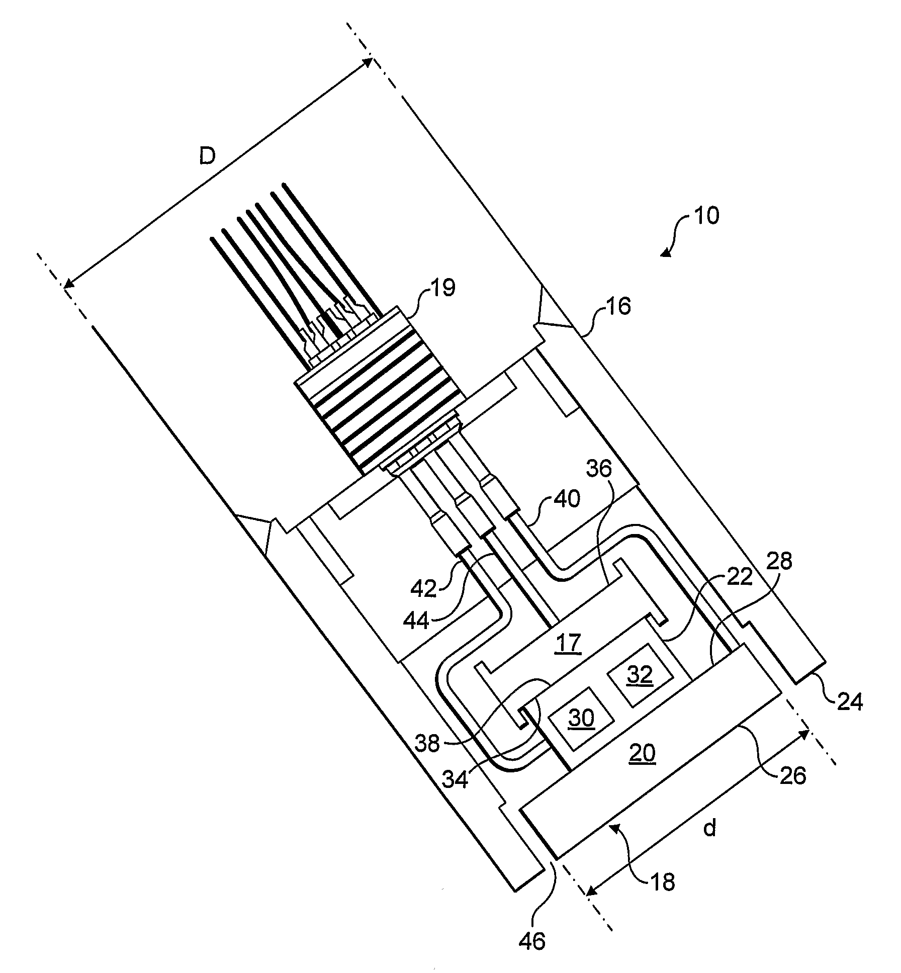
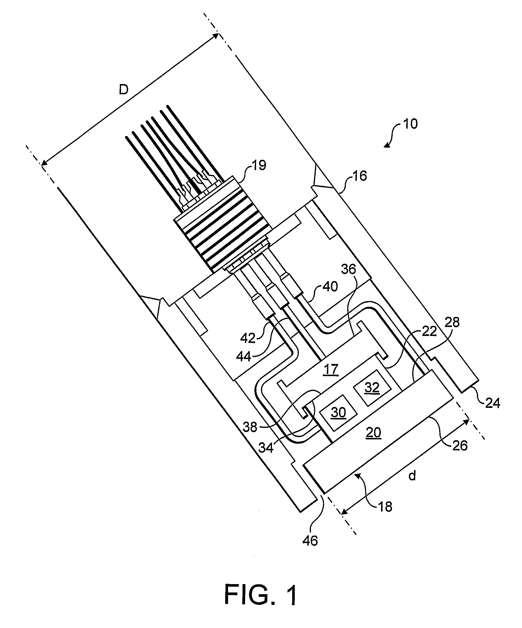
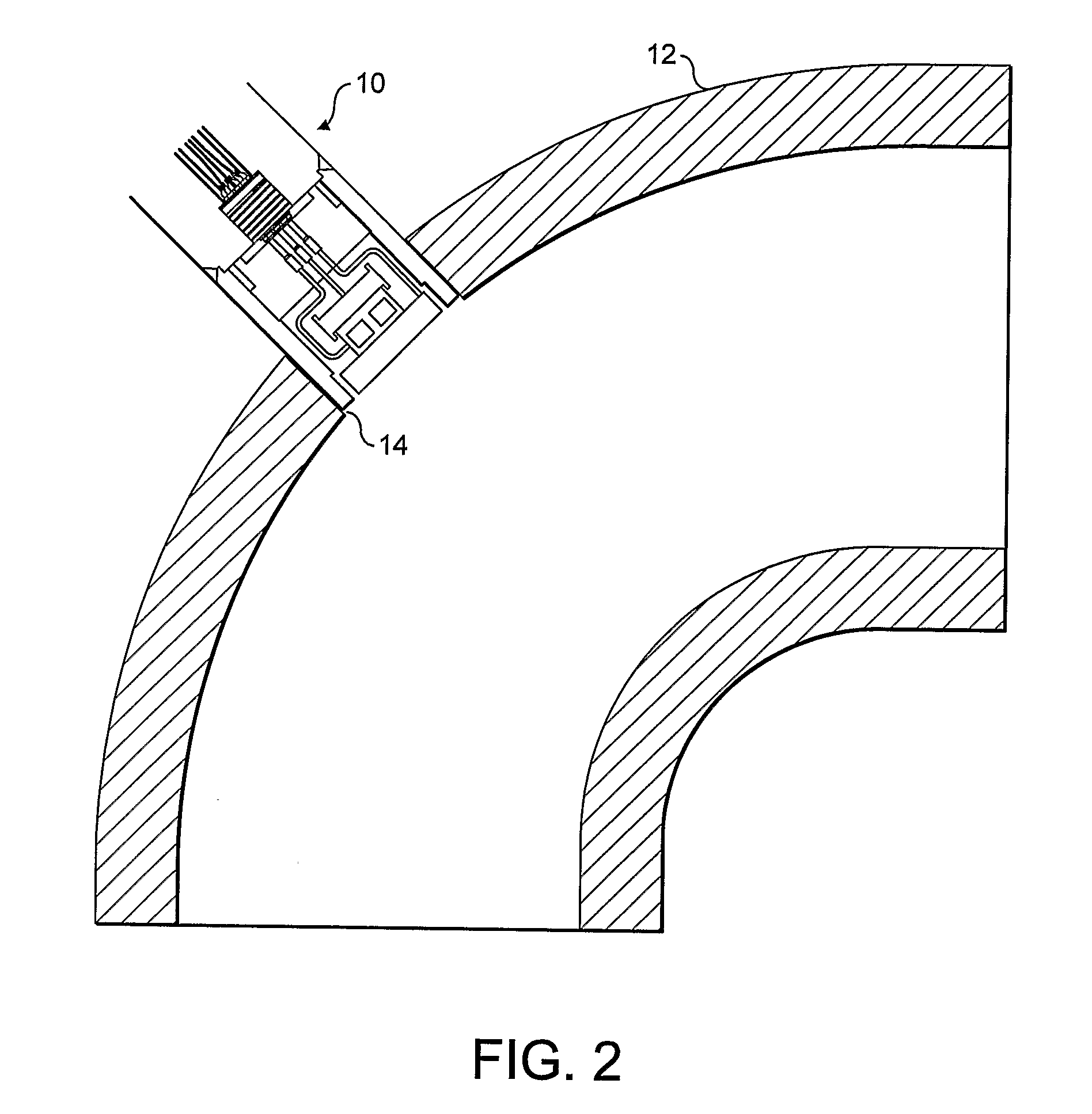
[0043]FIG. 1 shows a section through an apparatus according to one embodiment of the present invention. In FIG. 1 the apparatus is a probe 10 for monitoring particles in a fluid stream flowing through a conduit. The probe 10 is intended to be flush mounted on an external bend of a pipe 12, as shown in FIG. 2. Thus there is an opening 14 in the pipe 12 through which the probe 10 is inserted.

[0044]Referring to FIG. 1, the probe 10 comprises a probe housing 16 within which there is a differential pressure transducer 17 and a detector element 18. An electrical connector 19 located at the back of the probe 10 provides an output from the probe 10. The detector element 18 comprises a target portion 20 and an acoustic sensing portion 22. In a preferred embodiment, the detector element 18 is made of the same material as the inside surface of the pipe 12 so that it will corrode in the same way as the pipe 12. The target portion 20, the acoustic sensing portion 22, and the transducer 17 are ea...


PUM


Abstract

There is described an apparatus for monitoring particles in a fluid stream, comprising a body portion and a detector element that is acoustically decoupled from the body portion. The detector element comprises a target surface, a sample acoustic sensor and a corrosion sensor. The sample acoustic sensor is acoustically coupled to the target surface and is arranged to provide a first signal, which varies in dependence upon acoustic noise generated by impacts of particles and fluid on the target surface. The corrosion sensor is arranged to provide a second signal, which varies in dependence upon corrosion and/or erosion of the target surface. A corresponding method of monitoring particles in a fluid stream is also described. The method and apparatus are suitable for monitoring sand in oil and gas production flow streams.

Description

FIELD OF THE INVENTION[0001]The present invention relates to an apparatus for monitoring particles in a fluid stream, and to a method of monitoring particles in a fluid stream. In particular, the present invention relates to monitoring sand in oil and gas production flow streams.BACKGROUND OF THE INVENTION[0002]It is desirable to be able to monitor particles in a fluid flowing through a conduit. It is particularly desirable to be able to monitor formation sand that is entrained in oil and gas production flow streams. In such systems, the particles may influence erosion, erosion / corrosion and / or corrosion of the conduit surface, potentially leading to breaches of the conduit by the fluid. Therefore, it is important to be able to measure the metal loss of the conduit surface, especially at conduit bends where the metal loss rate is greatest. Nonetheless, it is also important to monitor metal loss on straight sections of a conduit. (It should be noted that, in the art, “corrosion” is a...

Claims


Application Information

Patent Timeline
IPC IPC(8): G01N15/06G01N29/02G01N25/00G01N17/04G01N29/032G01N29/22G01N29/30
CPCG01N29/222G01N29/30G01N2291/02408G01N2291/02827G01N2291/02836G01N2291/02872G01N15/06G01N17/04G01N29/032G01N29/02
Inventor HEMBLADE, BARRY JOHN
Owner TELEDYNE INSTR INC
Why Eureka
Try Eureka