Compression device for interlocking compression nailing systems and method of use

a compression nailing and compression device technology, applied in the direction of internal osteosynthesis, internal osteosynthesis, osteosynthesis devices, etc., can solve the problem of biocompatible materials that cannot be applied, and achieve the effects of improving bone healing development, preventing stress shielding effect, and simple design

Inactive Publication Date: 2016-11-01
ZEHTAB MOHAMMAD JAVAD +2
View PDF13 Cites 1 Cited by
  • Summary
  • Abstract
  • Description
  • Claims
  • Application Information

AI Technical Summary

Benefits of technology

[0014]The object of this invention is to introduce the “compression device” as an add-on for interlocking compression nailing systems which provides an active inherent compression force onto fracture site and whole bone fixed between proximal and distal part of nail to prevent stress shielding effect, improve bone healing development and emend deficiencies of interlocking compression nailing and similar devices known in the art. A further object of the invention is to create a compression device which is simple in design, inexpensive in manufacture, flexible in use, compatible with almost all of conventional interlocking compression nails, biocompatible enough to remain within implant for long terms and does not impose any additional invasive procedure on patients.
[0017]After gap minimization, further screwing of set screw merely compresses the elastic component longitudinally with regards to its elastic properties. In this way, compressed elastic component supplies an active reliable permanent compression onto fracture site and both bone fragments through providing desired force onto the shaft of proximal fastener screw.

Problems solved by technology

Moreover, this material is biocompatible enough to apply in long term implants.

Method used


Image

  • Compression device for interlocking compression nailing systems and method of use
  • Compression device for interlocking compression nailing systems and method of use
  • Compression device for interlocking compression nailing systems and method of use

Examples


example 1

[0039]Standard techniques of intramedullary nailing can be used for compression device application as it is briefly explained in coming sections. For simplicity and repetition avoidance, surgery procedures were not illustrated in drawings in step by step manner. Outlined were described only as needed to demonstrate the devices and methods while details of standard and known procedures and instruments are omitted.

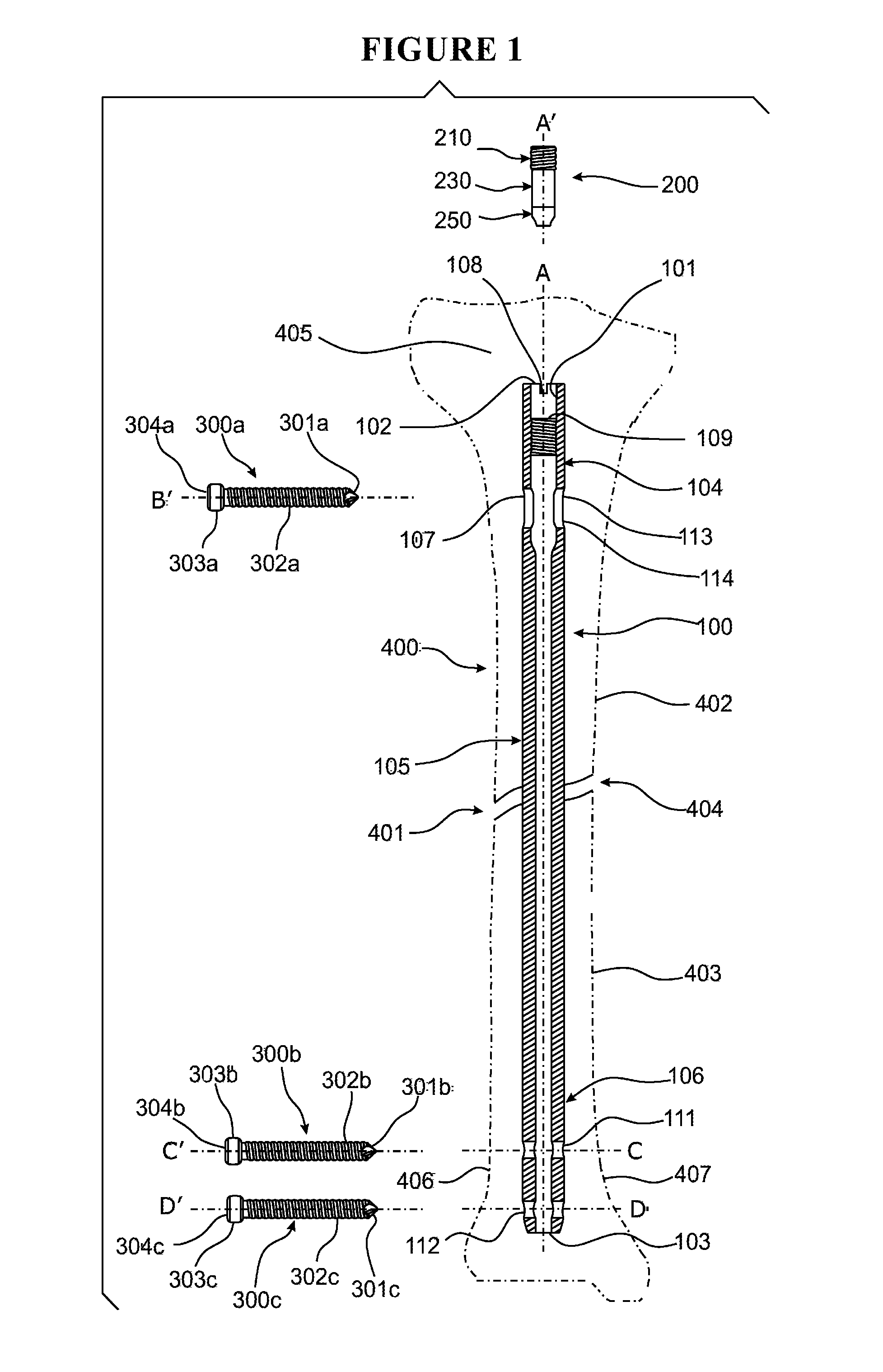
[0040]First, a standard midline patella tendon splitting approach is used for the affected limb. Second, the entry point is obtained using an awl (not shown). Then, reduction is achieved manually in order to bone fragments 402, 403 be aligned to each other. After that, a ball-tipped guide-wire (not shown) is inserted across the fracture site 401 to the distal bone fragment 403. Next, reaming is done over the guide-wire (not shown) slightly beyond the nail diameter. In this point, an intramedullary nail with appropriate length and diameter is selected. The nail 100 used for c...


PUM


Abstract

A compression device and method for interlocking compression nailing systems provide a compression force onto fracture site and a bone fixed between proximal and distal parts of intramedullary nail to prevent stress shielding and improve healing. The compression device having pre-assembled components of set screw, elastic component, distal cap and connector screw are rotated. After nail insertion, the nail is fixed to the bone fragments by inserting the fasteners into distal bores and proximal slot. The compression device is inserted within the bore of the nail. The set screw is screwed to move elastic component and distal cap to push the proximal bone fragment distally. Distal cap overlies on fastener screw shaft to spread compression forces in fastener screw surface to prevent stress concentration. After fracture gap minimization, the set screw is screwed further to compress elastic component to provide desired compression force.

Description

SPONSORSHIP STATEMENT[0001]The present invention is sponsored by Tehran University of Medical Sciences (TUMS) for international filing.THE FIELD OF INVENTION[0002]The present invention relates to a compression device as an add-on for interlocking compression nailing systems which are well known for treating a range of long bone disorders.BACKGROUND OF THE INVENTION[0003]For the first time, a reliable and successful method of intramedullary nailing was introduced by Kuntscher. To avoid axial and rotational instability, new generations of intramedullary nailing systems were interlocked proximally and distally. Nowadays the interlocking nailing is the method of choice for treating a range of long bone disorders used by trauma and orthopedic surgeons world widely. This method offers a device with excellent stability against the axial and rotational deformation, involves much less surgical exposure and reduces the risk of infection; however, it fails to exert a compression onto the fract...

Claims


Application Information

Patent Timeline
Patent Type & Authority Patents(United States)
IPC IPC(8): A61B17/58A61B17/72
CPCA61B17/7233A61B17/7225
Inventor ZEHTAB, MOHAMMAD JAVADLOTFALIANY ABRAND ABADI, MOJTABANAZARI NODOUSHAN, MORTEZA
Owner ZEHTAB MOHAMMAD JAVAD
Why Eureka
Try Eureka