
Electric motor systems and methods

a technology of electric motors and motors, applied in the direction of mechanical energy handling, magnetic circuit shape/form/construction, wellbore/well accessories, etc., can solve the problems of high pressure, large size of the esp, and inability to meet the requirements of downhole environments, etc., to achieve the effect of reducing the pressure differential

Active Publication Date: 2016-11-01
HENRY RES & DEV
View PDF6 Cites 0 Cited by
  • Summary
  • Abstract
  • Description
  • Claims
  • Application Information

AI Technical Summary

Benefits of technology

The patent describes an electric motor system and method that uses a permanent magnet motor. The motor has a specific design with different numbers of poles and slots, and the windings are positioned on the stator. The rotor has multiple magnets, and the motor may have a sealed lubricant chamber. The motor also has a pressure compensation device to minimize pressure differences between the lubricant and external fluids or gases. The technical effects of this design include increased efficiency, higher torque, and improved speed control.

Problems solved by technology

However, not all electric motors are suitable for downhole environments.
In harsh downhole environments, electric motors may be exposed to high pressure, high temperatures, fluids, mud, and other conditions that may impact operation of the motor.
Due to inherent motor inefficiencies, some ESP motors may require a minimum flow rate or speed of fluid moving past the motor housing to prevent the motor from overheating.
Additionally, the size of ESPs may be increased in order to compensate for motor inefficiencies by adding surface area to dissipate heat, but the resulting size of the ESP may be cumbersome.

Method used


Image

  • Electric motor systems and methods
  • Electric motor systems and methods
  • Electric motor systems and methods

Examples


Embodiment Construction

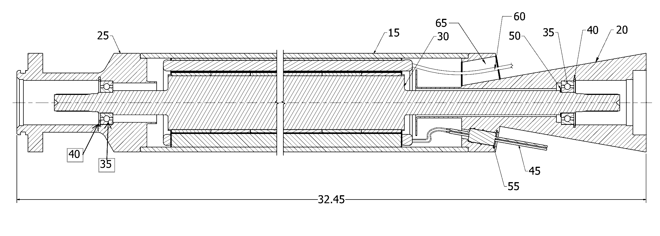
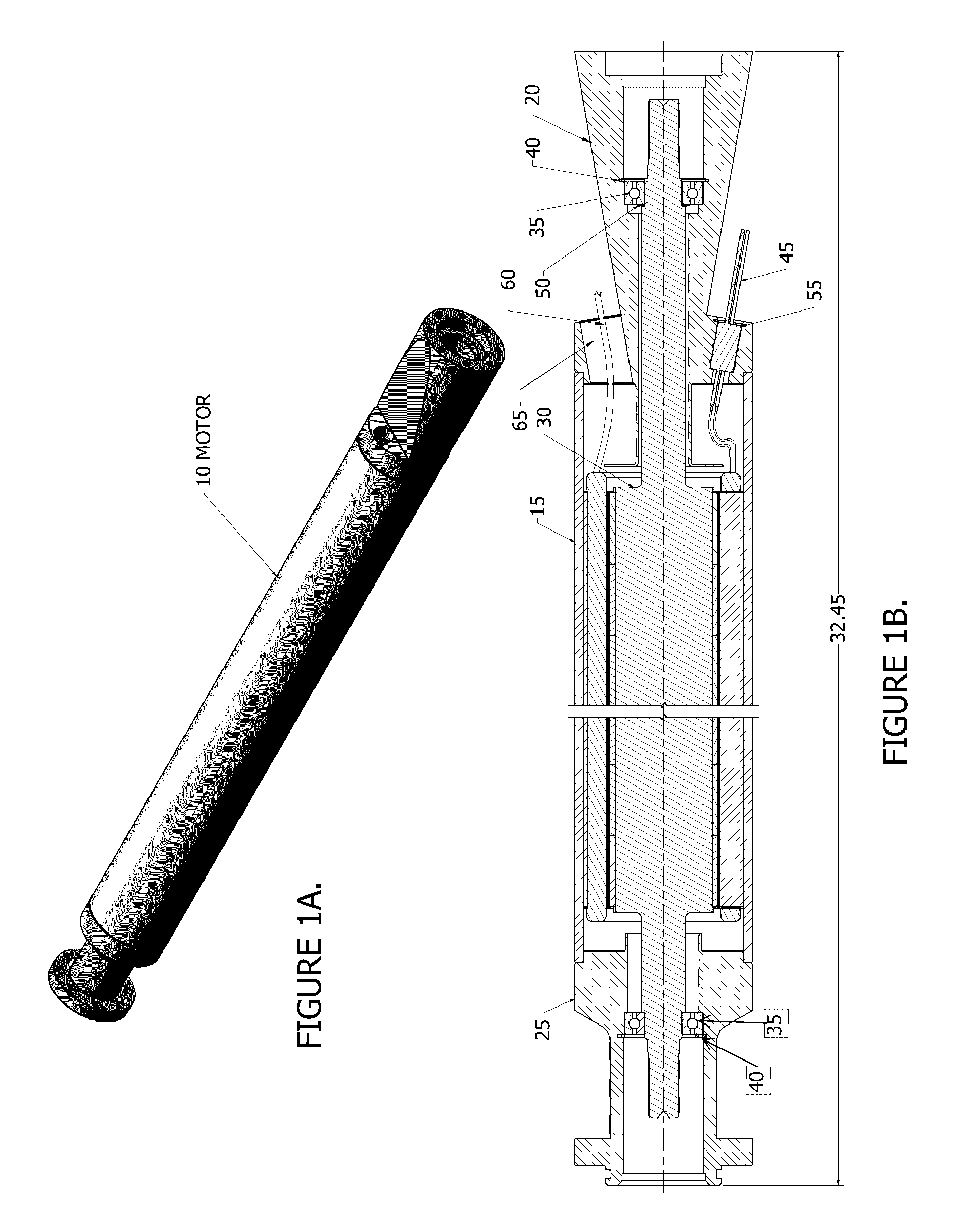
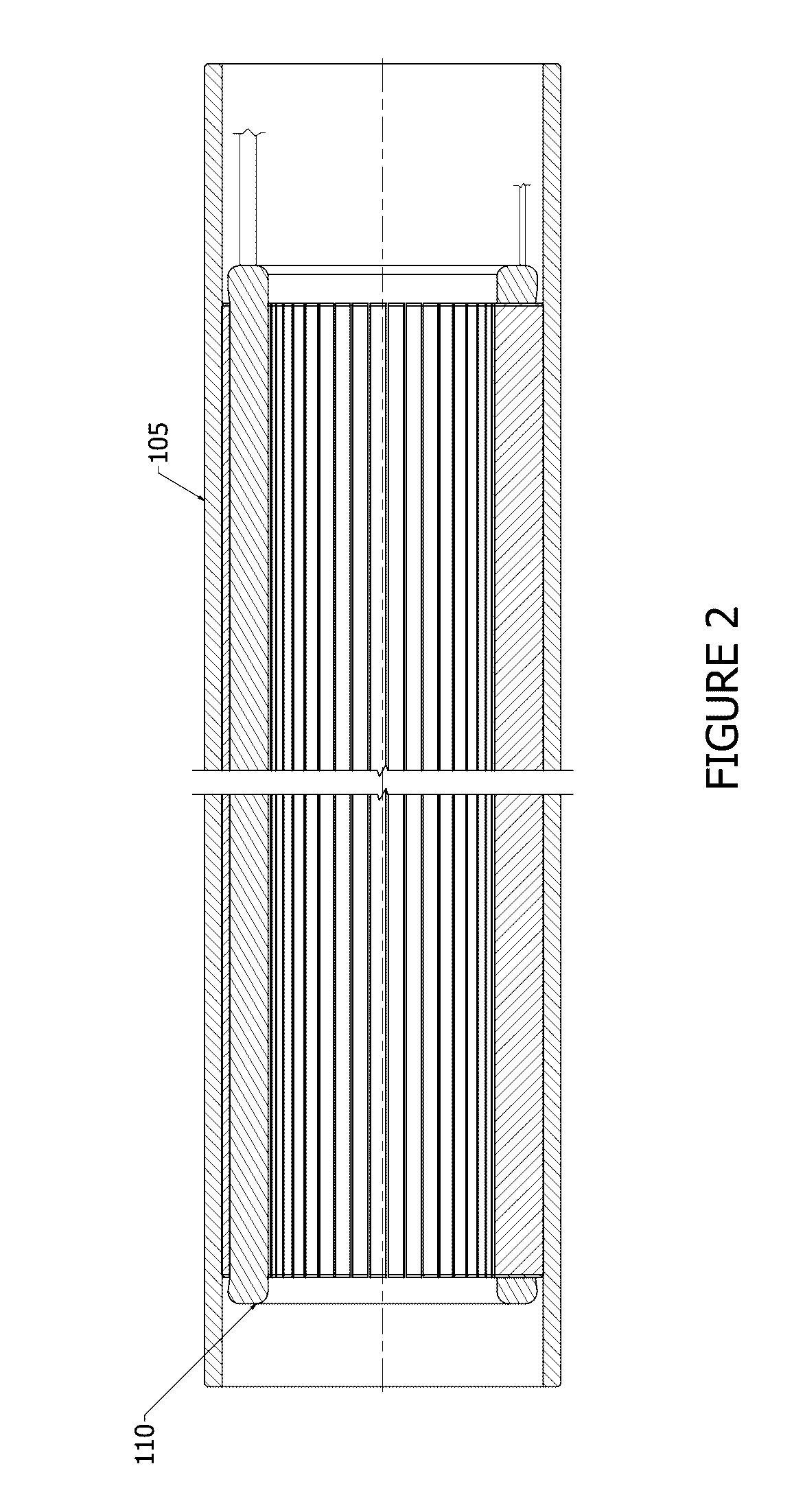
[0019]Refer now to the drawings wherein depicted elements are not necessarily shown to scale and wherein like or similar elements are designated by the same reference numeral through the several views.

[0020]Referring to the drawings in general, it will be understood that the illustrations are for the purpose of describing particular implementations of the disclosure and are not intended to be limiting thereto. While most of the terms used herein will be recognizable to those of ordinary skill in the art, it should be understood that when not explicitly defined, terms should be interpreted as adopting a meaning presently accepted by those of ordinary skill in the art.

[0021]It is to be understood that both the foregoing general description and the following detailed description are exemplary and explanatory only, and are not restrictive of the invention, as claimed. In this application, the use of the singular includes the plural, the word “a” or “an” means “at least one”, and the use...


PUM


Abstract

Electric motor systems and methods may provide highly efficient operation. The electric motor systems and methods discussed herein provide an oil filled motor that is low speed and utilizes permanent magnets. The electric motor may utilize a large number of poles and fractional slot design. Further, in some embodiments, the electric motor systems and methods may be suitable for use downhole.

Description

RELATED APPLICATIONS[0001]This application claims the benefit of U.S. Provisional Patent Application No. 61 / 749,475 to Hardway et al., filed on Jan. 7, 2013, which is incorporated herein by reference.FIELD OF THE INVENTION[0002]This invention relates to electric motor systems and methods. More particularly, to electric motors that are capable of operating in a downhole environment.BACKGROUND OF INVENTION[0003]Electric motors may be utilized downhole for various operations. However, not all electric motors are suitable for downhole environments. In harsh downhole environments, electric motors may be exposed to high pressure, high temperatures, fluids, mud, and other conditions that may impact operation of the motor.[0004]One example of motors utilized downhole are electric motors utilized in Electrical submersible pumps (ESPs) for pumping fluids from wells or the like. ESPs are centrifugal pumps that may be placed into a well to pump fluids. Due to inherent motor inefficiencies, some...

Claims


Application Information

Patent Timeline
Patent Type & Authority Patents(United States)
IPC IPC(8): H02K5/12E21B43/12H02K17/00H02K5/132
CPCH02K5/132E21B43/128H02K2213/03H02K2213/09H02K1/16H02K1/2706H02K7/083
Inventor HARDWAY, TREVORSALERNO, MICHAELWALLIN, RONALD DAVID
Owner HENRY RES & DEV
Learn More