Mflp-valve for a pressure source

Active Publication Date: 2017-02-16
MEDELA HLDG AG
View PDF3 Cites 0 Cited by
  • Summary
  • Abstract
  • Description
  • Claims
  • Application Information

AI Technical Summary

Benefits of technology

[0037]A system for extracting milk from a lactating human mother according to the present disclosure may include a breastpump, a pressure generating device including at least one of a piston and a diaphragm that generates pressure in the system, and a MFLP-valve that physically opens when the pressure generating device arrives at a return position

Problems solved by technology

The known pressure control mechanisms may require more than desired design complexity.
For example, the piston-cylinder/aperture design may limit the overall performance of the system.
The solenoid valve a

Method used


Image

  • Mflp-valve for a pressure source
  • Mflp-valve for a pressure source
  • Mflp-valve for a pressure source

Examples


Embodiment Construction

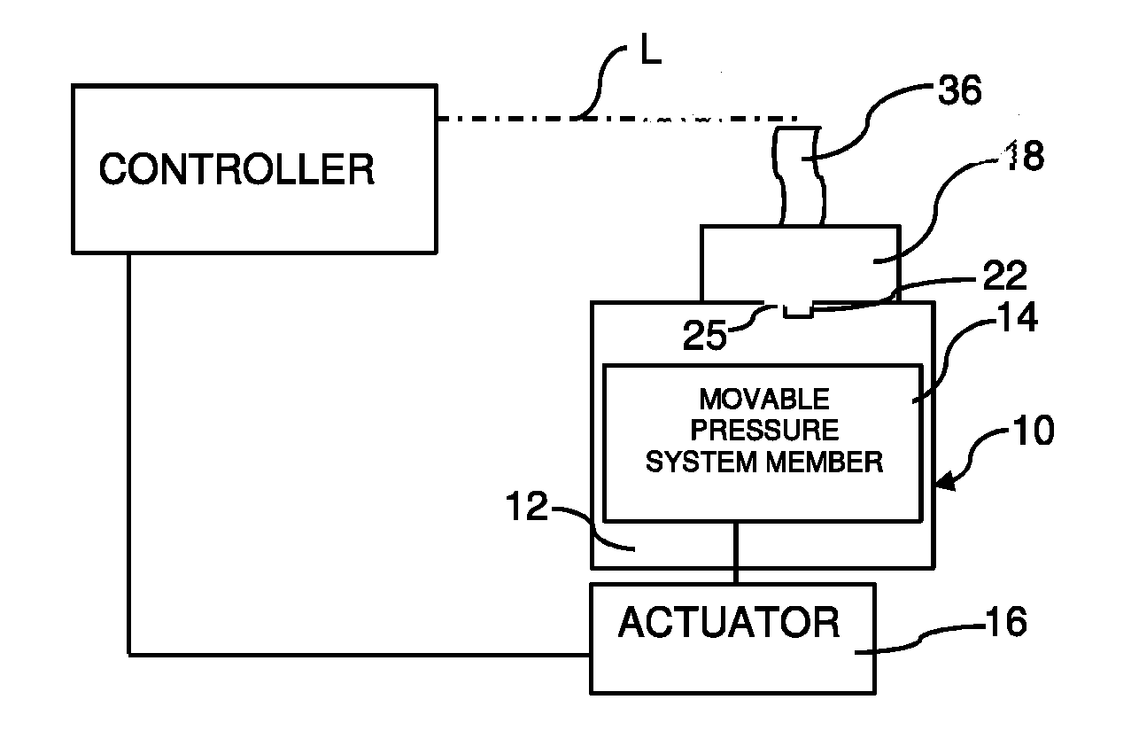
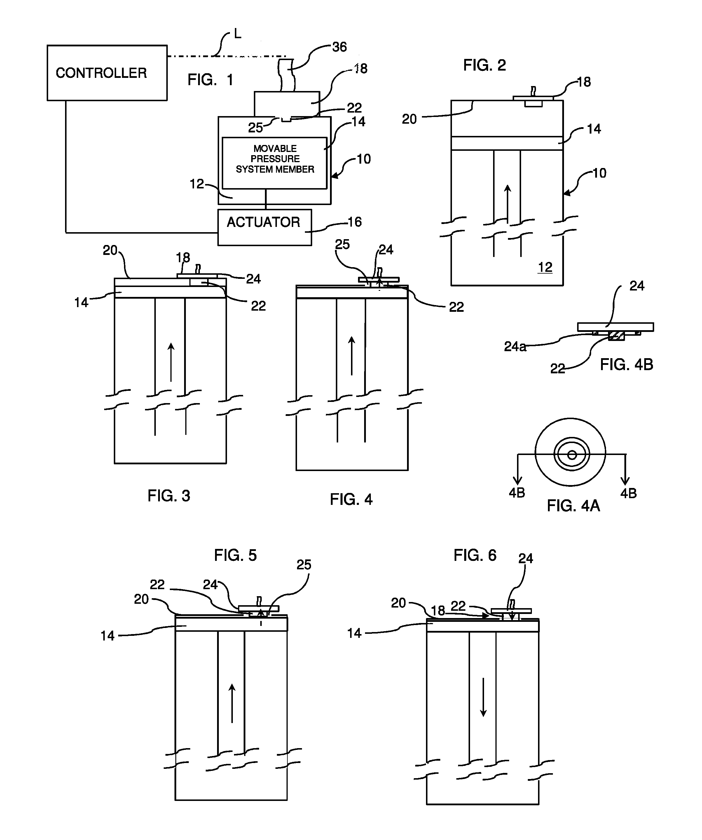
[0061]In accordance with the principles of the present disclosure, a pressure source, such as a pressure source 10 of a breastmilk expression device, for example, includes a pressure generating chamber 12 having a movable pressure system member 14 therein. The movable pressure system member may be actuated by an actuator 16, as illustrated in FIG. 1. A MFLP-valve 18 is associated with an end wall of the pressure generating chamber 12. As used herein, the term “MFLP-valve” refers to a pressure modification valve that can be configured to be coupled with a sensor flag, either directly or indirectly. The MFLP-valve 18 can be secured in a sealed relationship with an aperture 25 in a wall of the pressure generating chamber 12, or can otherwise be positioned as desired on or near the pressure generating chamber 12 or connected to a connector or tubing extending from the pressure generating chamber 12. In an embodiment, the MFLP-valve 18 can be displaced from a sealed condition to an unsea...


PUM


Abstract

A mechanical fluid pressure modification valve, or “MFLP-valve”, is set forth. The MFLP-valve can be actuated upon movement of a movable pressure system member of a medical pressure system reaching a selected position. Additionally, the MFLP-valve can be actuated based on a pressure condition of the system. When the MFLP-valve unseals, a pressure differential between a pressure chamber and a volume outside of the chamber can be relieved. Disengagement of the movable pressure system member from the MFLP-valve can enable the MFLP-valve to re-seal. The MFLP-valve may include a flag that indicates the position of the movable pressure system member. The MFLP-valve may be provided in a diaphragm-type pressure source.

Description

CROSS-REFERENCE TO RELATED APPLICATION[0001]This application claims priority to U.S. Provisional Patent Application No. 62 / 205,419 filed Aug. 14, 2015 entitled “MFLP-Valve for a Pressure Source,” the entire disclosure of which is hereby expressly incorporated by reference herein.FIELD OF THE DISCLOSURE[0002]The present disclosure relates generally to pressure systems, such as breastmilk expression systems, including breastpumps, and, more particularly, to a mechanical fluid pressure modification valve (hereinafter MFLP-valve) that provides relief and / or intake for fluid in a pressure system, and that may be used in combination with a flag selectively detected by a sensor.BACKGROUND[0003]Pressure systems, such as breastmilk expression systems, have been disclosed that include mechanisms to selectively modify pressure within the system. For instance, U.S. Pat. No. 5,007,899 discloses a breastpump with a piston pump having an aperture in a piston cylinder. The breastpump exposes the va...

Claims


Application Information

Patent Timeline
IPC IPC(8): A61M1/06A61M39/22
CPCA61M1/062A61M2205/332A61M39/227A61M1/06F16K15/18A61M1/742A61M1/81A61M1/06935A61M2205/3331A61M2205/3337A61M2039/2486
Inventor GIST, JAHICHO, DAVIDRIGERT, MARIO
Owner MEDELA HLDG AG
Why Eureka
Try Eureka