[0005]The discharged airflows are fed into a common suction tube. This saves on mounting space compared with a system where a separate suction tube is provided for every
cyclone. At the same time, fewer components are needed. However, using the common suction tube does mean that suction paths from the individual cyclones will necessarily be of differing lengths. When the airflows are remerged with one another, significant pressure differences are generated as a result, which can considerably reduce the suction power and hence the separating efficiency. In order to guarantee that dirt is sucked away efficiently, a system is therefore proposed whereby the airflows from the cyclones are merged again in respective pairs. Remerging the airflows in respective pairs reduces the
resultant pressure differences. As a result, the same
vacuum pressure and
mass flow can be obtained at every
cyclone.
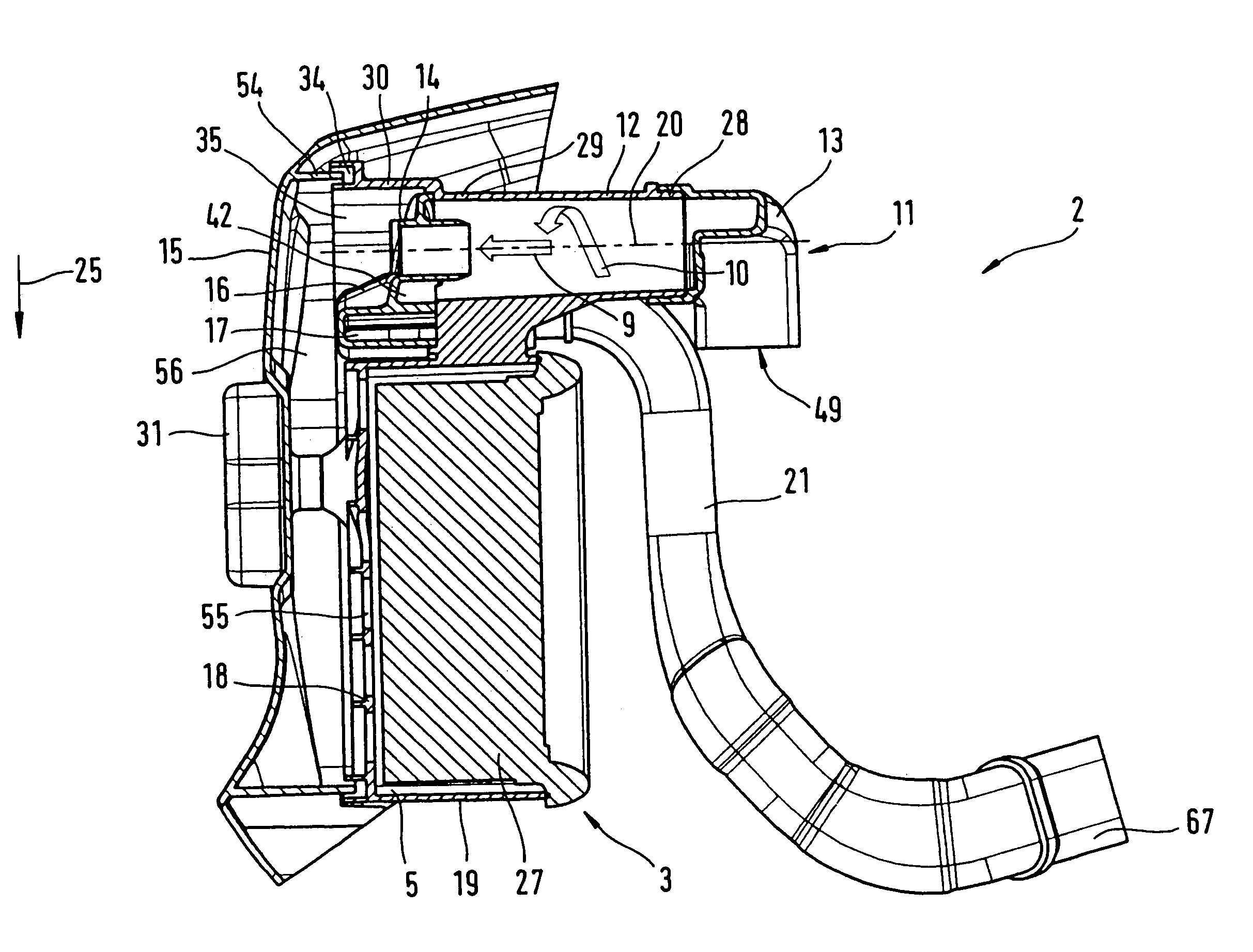
[0007]For practical purposes, the dirt collection chamber has a flow-connection to the
peripheral flow leaving the cyclones, which has a high
particle density. At least one
cyclone advantageously has an immersion tube, provided on the end of the main body remote from the intake element, through which the core flow leaves the cyclone. In particular, the immersion tubes for all cyclones are provided as an integral part of the dirt collector. This therefore dispenses with the need for any other separate components. The fact that the immersion tubes are an integral part of the dirt collector makes for a compact construction. The dirt collection chamber in the dirt collector advantageously extends substantially transversely to the longitudinal axis of the cyclone.
[0008]Every cyclone advantageously has a main body with an intake element adjoining it. The intake element is specifically provided as a separate part. The intake element can therefore be manufactured separately. This duly simplifies the component geometries to be manufactured. Particularly in the case of centrifugal separators made from plastic, production can be simplified by using an
injection molding process. However, it may also be of
advantage to make the intake element as an integral part of the main body. To make the centrifugal separator easy to retrofit in existing housings, it is proposed that the centrifugal separator should have at least two, in particular at least three, cyclones. This enables a sufficient
throughput of combustion air to be generated without the need for a large contiguous construction volume. In order to obtain efficient intake, the intake element has an inlet funnel.
[0009]The intake element is advantageously joined to the main body in a snap-fit connection. This makes for a simple
assembly system. In particular, a catch connection is provided between intake element and main body. The intake elements may also be fixed onto the main body by additional means, such as
welding for example. The number of parts is kept low if the intake elements for all cyclones are of an identical design. This makes production and warehouse storage less complex. However, it may also be expedient to design the intake elements as an integral part of the main bodies of the cyclones. The number of parts needed can also be reduced if the air filter is disposed in an air filter housing and the main bodies of the cyclones constitute a common component in conjunction with a first housing part of the air filter housing. This enables the cyclones to be produced in a
single process step together with the air filter housing. This is easily done by providing the intake elements separately and manufacturing them by an
injection molding process in particular. One particularly advantageous embodiment can be obtained by incorporating the dirt chamber of the air filter in the first housing part of the air filter housing.
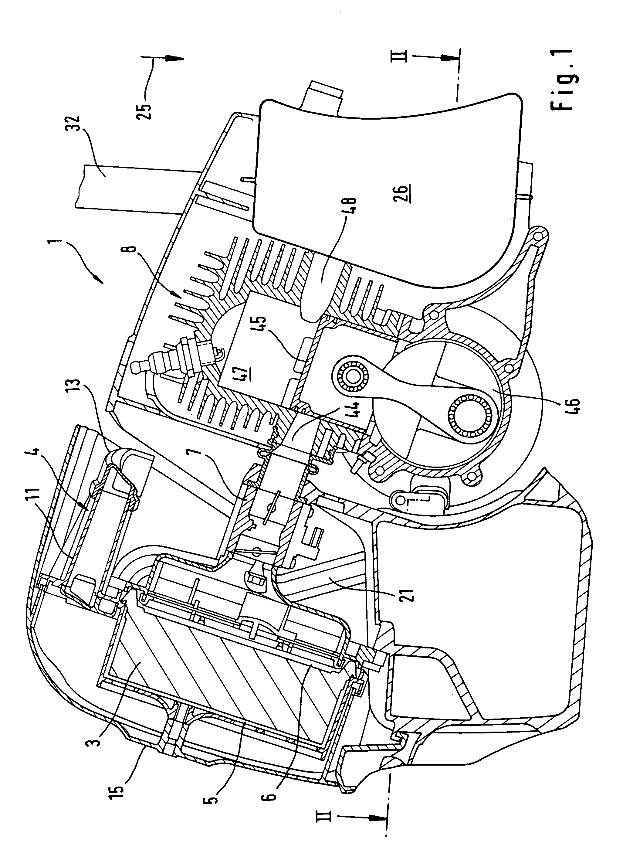
[0012]Advantageously, the main bodies of the cyclones are approximately cylindrical, in particular slightly conical. Opting for a slightly conical design will facilitate mold release of the main body after the
injection molding process. An advantageous arrangement can be obtained if the longitudinal axes of the cyclones extend parallel with one another and form a plane. By reference to the direction of
gravitational force, the intake elements specifically draw in combustion air from above the
carburetor. In this region, the air is charged with a low proportion of particles, which means that the main flow leaving the cyclones contains few particles, ensuring that the air filter will have a long service life. In one particularly advantageous embodiment, the intake system proposed by the invention is used in a disc grinder.

