Magnetic tape having characterized backcoat layer and method of manufacturing the same

a backcoat layer and magnetic tape technology, applied in the field of magnetic tapes, can solve the problems of edge damage, edge damage, edge damage, etc., and achieve the effect of low dropout and high electromagnetic characteristics

Active Publication Date: 2019-11-12
FUJIFILM CORP
View PDF335 Cites 38 Cited by
  • Summary
  • Abstract
  • Description
  • Claims
  • Application Information

AI Technical Summary

Benefits of technology

[0007]Examples of characteristics that are demanded of magnetic tapes are high electromagnetic characteristics and low dropout.
[0008]One effective way to enhance the electromagnetic characteristics is to increase the smoothness of the magnetic tape surface (surface on the magnetic layer side).
[0010]However, when the smoothness of the surface on the backcoat layer side is increased, the edges of the magnetic tape tend to be damaged (referred to as “edge damage” hereinafter) after being run in a drive. This will be described further. Recording and reproducing a signal on a magnetic tape are conducted by setting a magnetic tape cartridge housing a magnetic tape in a drive and running the magnetic tape within the magnetic tape cartridge. The magnetic tape is housed within the magnetic cartridge by being wound up on a reel. Thus, during running, the magnetic tape is fed out from and wound up on the reel. When misalignment occurs during this winding, the edge of the magnetic tape strikes the flange and the like of the reel, and edge damage ends up occurring. This edge damage can cause an increase in errors during recording and a drop in running stability. Accordingly, it is desirable to inhibit edge damage by inhibiting winding misalignment in addition to decreasing dropout and enhancing the electromagnetic characteristics.
[0011]An aspect of the present invention provides for a magnetic tape that can exhibit good electromagnetic characteristics and make it possible to inhibit dropout and edge damage.
[0021]The above magnetic tape can exhibit good electromagnetic characteristics, permit the reading of signals with little dropout, and can be run with little edge damage. The presumptions of the present inventors in this regard are set forth further below.
[0046]An aspect of the present invention can provide a magnetic tape exhibiting good electromagnetic characteristics, in which dropout and edge damage are inhibited.

Problems solved by technology

However, when the smoothness of the surface on the backcoat layer side is increased, the edges of the magnetic tape tend to be damaged (referred to as “edge damage” hereinafter) after being run in a drive.
When misalignment occurs during this winding, the edge of the magnetic tape strikes the flange and the like of the reel, and edge damage ends up occurring.
This edge damage can cause an increase in errors during recording and a drop in running stability.

Method used


Image

  • Magnetic tape having characterized backcoat layer and method of manufacturing the same

Examples


example 1

[0188]A 3.0 part quantity of 2,3-dihydroxynaphthalene (made by Tokyo Chemical Industry Co., Ltd.), 31.3 parts of a 32% solution (with a mixture of methyl ethyl ketone and toluene as solvent) of polyester polyurethane resin (UR-4800 (polar group quantity: 80 meq / kg) made by Toyobo (Japanese registered trademark)), and 570.0 parts of a solvent in the form of a 1:1 (weight ratio) mixed solution of methyl ethyl ketone and cyclohexanone were mixed with 100.0 parts of alumina powder (HIT-70 made by Sumitomo Chemical Company, Ltd. having an alpha conversion rate of above 65% and a BET specific surface area of 30 m2 / g) and the mixture was dispersed for 5 hours in a paint shaker in the presence of zirconia beads. Following dispersion, the dispersion and the beads were separated with a mesh, yielding an alumina dispersion.

[0189]2. Formula of Magnetic Layer-Forming Composition

[0190]

(Magnetic liquid)Ferromagnetic hexagonal barium ferrite powder100.0partsFerromagnetic hexagonal barium ferrite po...

examples 2 to 13

, Comparative Examples 1 to 11

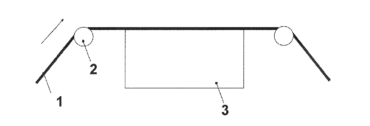
[0202]With the exceptions that the formulas of the various layer-forming compositions and / or manufacturing conditions were changed to those shown in Table 1, magnetic tapes were prepared by the same method as in Example 1. The period during which vibration was imparted was adjusted by changing the conveyance speed of the support on which the coating layers were formed.

[0203]The blending ratio of inorganic powder / carbon black in the backcoat layer recorded in Table 1 is the content based on weight of the various powders relative to 100.0 weight parts of the combined content of inorganic powder and carbon black.

[0204]The blending ratio of ferromagnetic hexagonal barium ferrite powder recorded in Table 1 is the content based on weight of the various ferromagnetic hexagonal barium ferrite powders relative to 100.0 weight parts of the total quantity of ferromagnetic powder. The average particle size of the ferromagnetic hexagonal barium ferrite powder shown ...


PUM

PropertyMeasurementUnit
surface roughnessaaaaaaaaaa
surface roughness Raaaaaaaaaaa
full width at half maximumaaaaaaaaaa

Abstract

The magnetic tape has a magnetic layer and a backcoat layer. The Ra on the magnetic layer side surface is less than or equal to 1.8 nm, the coefficient of friction measured on the base portion of the magnetic layer side surface is less than or equal to 0.35, and the Ra measured on the backcoat layer side surface is less than or equal to 5.0 nm. The backcoat layer contains a fatty acid ester. In addition, the FWHMbefore measured on the backcoat layer side surface before vacuum heating is greater than 0 nm but less than or equal to 10.0 nm, the FWHMafter after vacuum heating is greater than 0 nm but less than or equal to 10.0 nm, and the difference between the spacing measured on the backcoat layer side surface after and before vacuum heating is greater than 0 nm but less than or equal to 8.0 nm.

Description

CROSS-REFERENCE TO RELATED APPLICATIONS[0001]This application claims priority under 35 U.S.C 119 to Japanese Patent Application No. 2016-018821 filed on Feb. 3, 2016. The above application is hereby expressly incorporated by reference, in its entirety.BACKGROUND OF THE INVENTION[0002]Field of the Invention[0003]The present invention relates to a magnetic tape and a method of manufacturing the same.[0004]Discussion of the Background[0005]Magnetic recording media include tape-shaped media and disk-shaped media. Magnetic recording media in the form of tapes, that is, magnetic tapes, are primarily employed in storage applications such as data-backup tapes.[0006]Japanese Unexamined Patent Publication (KOKAI) No. 2004-5820, which is expressly incorporated herein by reference in its entirety, discloses a magnetic tape having a backcoat layer (referred to in Japanese Unexamined Patent Publication (KOKAI) No. 2004-5820 as a “back layer”) on the opposite side of the nonmagnetic support from t...

Claims


Application Information

Patent Timeline
Patent Type & Authority Patents(United States)
IPC IPC(8): G11B5/73G11B5/70G11B5/84G11B5/78G11B5/735G11B5/733G11B5/008
CPCG11B5/735G11B5/8404G11B5/78G11B5/733G11B5/73G11B5/70G11B5/8412G11B5/00813G11B5/7358
Inventor OYANAGI, MASAHITOKASADA, NORIHITOOZAWA, EIKI
Owner FUJIFILM CORP
Why Eureka
Try Eureka