Electromagnetic wave lens, electromagnetic wave lens production method and lens antenna

An electromagnetic wave and lens technology, applied in the direction of antennas, electrical components, etc., can solve the problems of single hot-melt material, high cost, heavy installation and use difficulties, etc., and achieve the effect of compact and stable structure, high product consistency, and good electromagnetic characteristics

Active Publication Date: 2021-08-27
FOSHAN CITY EAHISON COMM
View PDF6 Cites 7 Cited by
  • Summary
  • Abstract
  • Description
  • Claims
  • Application Information

AI Technical Summary

Problems solved by technology

[0005] The production of wrapped structures usually requires the use of molds. If there are too many layers, the process is too complicated and the cost is high, and the performance consistency of different individuals is usually poor
[0006] Although the number of layered layers of the rolling structure is easy to make more layers, the existing technology can only make it into a cylinder or an ellipse cylinder instead of a sphere in the classical model, and in the middle of the cylinder and the ellipse cylinder The axial direction does not conform to the theory of the classical model, which greatly reduces its performance effect, so that it cannot meet the performance requirements in many scenarios
[0007] Holes are usually made by 3D printing, and the 3D printed structures are usually a single hot-melt material. The hot-melt materials suitable for 3D printing are either inappropriate in dielectric constant or low in density. , when faced with the production of large-scale lenses, its weight is considerable so that it causes various difficulties in installation and use

Method used


Image

  • Electromagnetic wave lens, electromagnetic wave lens production method and lens antenna
  • Electromagnetic wave lens, electromagnetic wave lens production method and lens antenna
  • Electromagnetic wave lens, electromagnetic wave lens production method and lens antenna

Examples


Embodiment 1

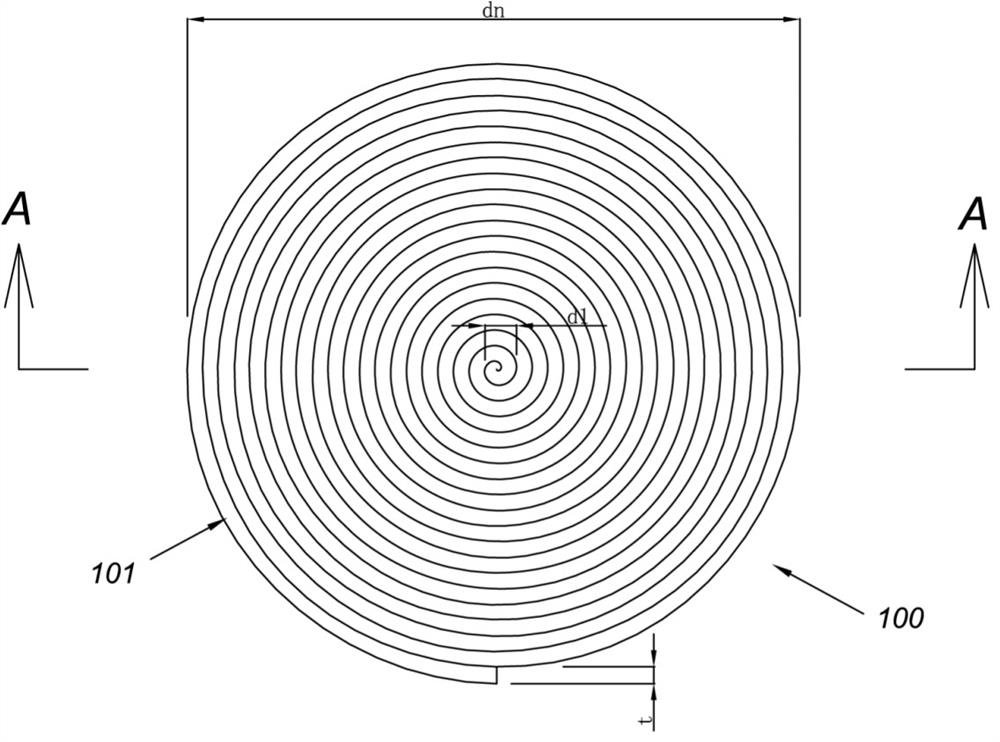
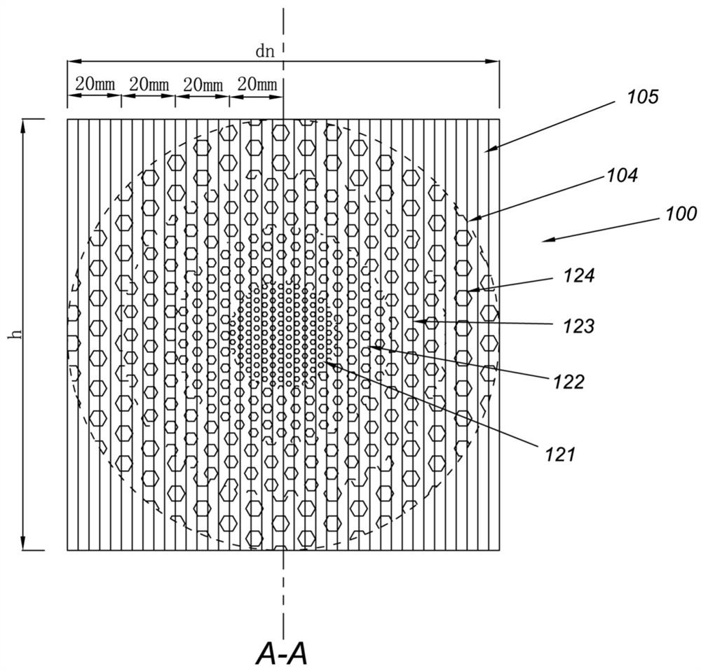
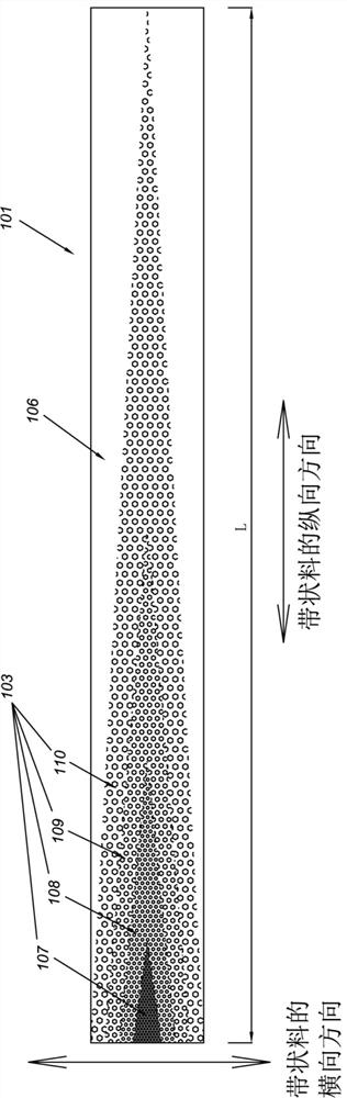
[0098] Present embodiment is the production method of electromagnetic wave lens and electromagnetic wave lens, as figure 1 , figure 2 As shown, the electromagnetic wave lens is a cylindrical rolled body 100 rolled from a strip material 101, as image 3 As shown, since the medium material is distributed on the surface of the strip material 101, and the medium material is distributed in a region of a specific shape, such a region is called the medium distribution area 103, and the strip material 101 is made into a rolled body After 100, the dielectric material will be distributed in an artificially predetermined spherical range inside the rolling body 100, and the spherical range where the dielectric material is distributed is the lens body 104 of the electromagnetic wave lens of this embodiment. The parts other than the lens body 104 of the rolled body 100 are referred to as non-lens parts 105 . The non-lens portion 105 is formed by the non-dielectric distribution area 106 o...

Embodiment 2

[0116] Such as Figure 7 As shown, this embodiment is an electromagnetic wave lens, and the rolled body 200 adopts the rolling method and structure of Embodiment 1, but two spherical lens bodies 201 of the same size are formed inside the rolled body 200, and the two lenses The bodies 201 are located at the two ends of the cylinder respectively. In the two lens bodies 201, all the dielectric constants are getting lower and lower from the inside to the outside. The two lens bodies 201 are arranged along the central axis direction of the rolled body 200 .

Embodiment 3

[0118] Such as Figure 8 , Figure 9 As shown, this embodiment is an electromagnetic wave lens, and the rolling body 300 is a quadrangular prism, and a spherical lens body 301 is formed inside the rolling body 300 . In the lens body 301 , the dielectric constant becomes lower and lower in all directions from the inside to the outside, and the central axis of the lens body 301 coincides with the central axis of the rolled body 300 .


PUM


Abstract

The invention provides a better electromagnetic wave lens, a production method and a lens antenna. The electromagnetic wave lens is a rolled body formed by rolling a strip-shaped material; dielectric constants of a dielectric materials are gradually changed in the transverse direction and the longitudinal direction of the strip-shaped material; after the strip-shaped material is rolled into the rolled body, the dielectric material is distributed in at least one predetermined three-dimensional space range in the rolled body, and the rolled body is called a lens body; the part, except the lens body, of the rolled body is called as a non-lens part; the dielectric constant in the lens body is not lower than that of the non-lens part; in the lens body, dielectric constants in all directions from inside to outside are lower and lower, and the directions from inside to outside refer to the direction from the central area of the lens body to the boundary of the lens body. The invention has the advantages of good electromagnetic property, high product consistency, high production efficiency, suitability for wide target sizes, compact and stable structure, and realization of single entity and multiple lenses.

Description

technical field [0001] The invention relates to the field of communication equipment production, more specifically, to an electromagnetic wave lens, a production method of the electromagnetic wave lens and an electromagnetic wave lens antenna. Background technique [0002] The Luneberg lens was proposed by RK Luneberg in 1944 based on the geometrical optics method. It is used as an antenna and scatterer, mainly used in fast scanning systems, satellite communication systems, automotive anti-collision radars, radar reflectors and other fields. [0003] The classic model of Lunberg lens is: from the center of the sphere to the outer diameter of the Lunberg lens, the dielectric constant should change continuously from 2 to 1 in accordance with certain mathematical laws. However, such an ideal structure does not exist in nature, so in practical design, a layered structure with step-change dielectric constant is often used to approximate the theoretical structure. [0004] In the...

Claims


Application Information

Patent Timeline
Patent Type & Authority Applications(China)
IPC IPC(8): H01Q15/08H01Q19/06
CPCH01Q15/08H01Q19/06
Inventor 郑洪振芦永超孙耀志李家铎李涛
Owner FOSHAN CITY EAHISON COMM
Why Eureka
Try Eureka