Double diaphragm pump

a diaphragm pump and diaphragm technology, which is applied in the direction of flexible member pumps, machines/engines, and positive displacement liquid engines, etc., can solve the problems of disassembly of valves and consequently the entire pump, rapid wear of diaphragms, and high differential pressure, and achieve low differential pressure, good level of efficiency, and long service life

Inactive Publication Date: 2013-04-25
PROMERA
View PDF8 Cites 37 Cited by
  • Summary
  • Abstract
  • Description
  • Claims
  • Application Information

AI Technical Summary

Benefits of technology

[0008]An object of the present invention is to provide a diaphragm pump in which the diaphragms have a long service-life and are subjected to low differential pressures and which has a good level of efficiency.

Problems solved by technology

The disadvantage of this pump is that the diaphragms, owing to the high pressure in the conveying space and the ambient pressure behind the diaphragm, are subjected to a high differential pressure load, which leads to rapid wear in the diaphragms.
The disadvantage of this pump is that, in the event of a defect of the diaphragm, the conveying medium reaches the pneumatic system and disables the valves and consequently the entire pump.
The pump can subsequently be restarted, if at all, only with great complexity.
The disadvantage of this pump involves the large spaces which must be filled with compressed air after the dead centre point has been reached so that the diaphragms can be moved in the other direction.
A very large amount of compressed air is thereby required, which increases the maintenance costs of the pump.

Method used


Image

  • Double diaphragm pump
  • Double diaphragm pump
  • Double diaphragm pump

Examples


Embodiment Construction

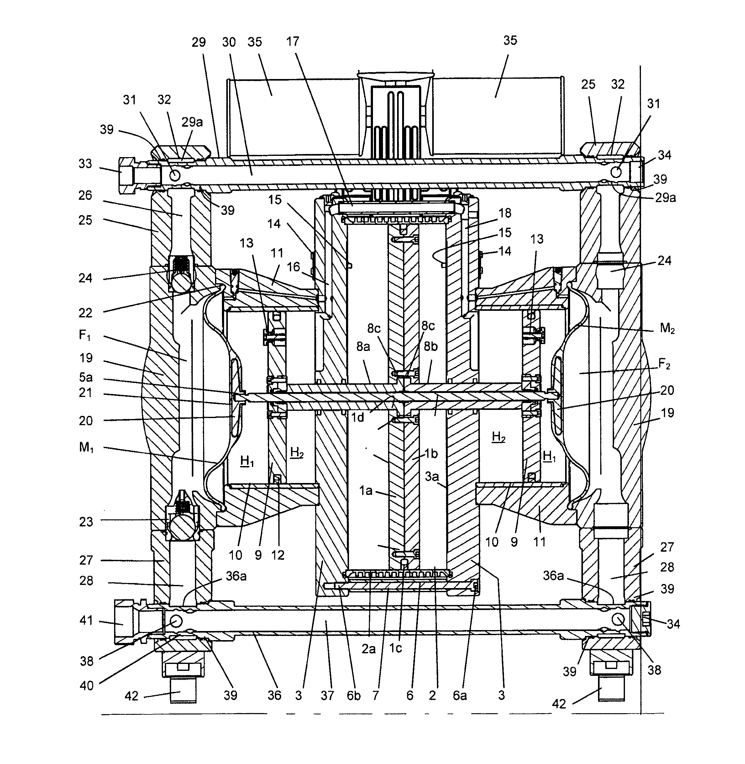
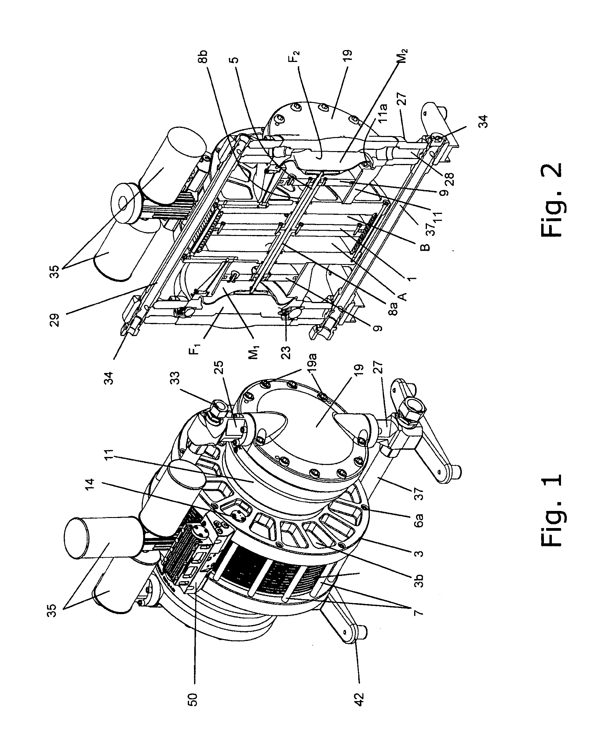
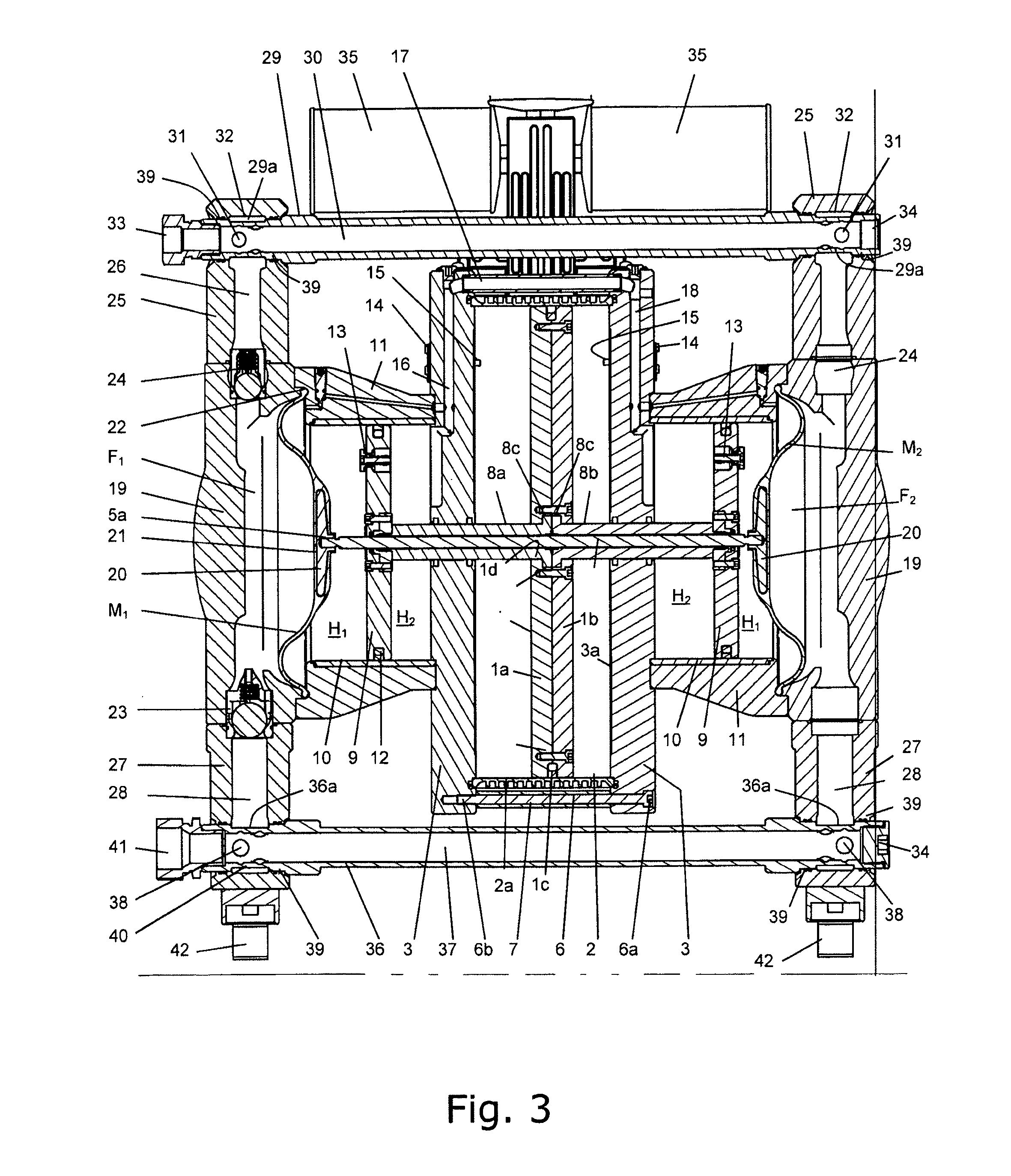
[0037]FIGS. 1 and 2 are perspective views of the diaphragm pump according to the invention in the form of a dual-diaphragm pump. The dual-diaphragm pump has a housing cover 19 and a housing portion 11 which receives the cylinder 10 of the hydraulically acting piston / cylinder system 9, 10. The housing portion 11, as illustrated in FIG. 2, is secured by means of coaxial screws 11a to the axial cylinder wall 3 of the first piston / cylinder system. The diaphragm M is clamped at 22 by the housing cover 19 and the housing portion 11 (see FIGS. 3 and 4). The housing cover 19 and housing portion 11 are connected to each other by means of the screws 19a and fix the diaphragm M in position. The housing cover 19 forms at the top and bottom a receiving member for a non-return valve 24, respectively. The non-return valves 23, 24 are inserted before the housing flanges 25, 27 are screwed to the housing cover 19 into the corresponding recesses of the housing cover 19. Additional seals prevent conve...


PUM


Abstract

A diaphragm pump, in which a fluid moves at least a first piston of a first piston/cylinder system back and forth, the first piston being mechanically connected to at least one other hydraulic piston and the hydraulic piston driving at least one diaphragm by a hydraulic medium.

Description

CROSS REFERENCE TO RELATED APPLICATIONS[0001]This application is the U.S. National Phase Patent Application of PCT International Application No. PCT / EP2011 / 001360, filed Mar. 18, 2011, which claims priority to German Patent Application No. 10 2010 013 108.3, filed Mar. 26, 2010, the contents of such applications being incorporated by reference herein.FIELD OF THE INVENTION[0002]The present invention relates to a diaphragm pump having at least one diaphragm.BACKGROUND OF THE INVENTION[0003]In diaphragm pumps, the diaphragm delimits a conveying space in which a supply line and a discharge line open. Generally, non-return valves are arranged in the supply and discharge lines in such a manner that, by the diaphragm being moved back and forth, the conveying medium can first be drawn via the supply line into the conveying space and can subsequently be pressed out of the conveying space via the discharge line.[0004]So that a continuous conveying action is possible, in most cases two diaphr...

Claims


Application Information

Patent Timeline
Patent Type & Authority Applications(United States)
IPC IPC(8): F04B43/06
CPCF04B43/026F04B43/06F04B43/073
Inventor SCHUTZE, THOMAS
Owner PROMERA
Why Eureka
Try Eureka